USER’S MANUAL SWITCHING-MODE DC POWER SUPPLY ARRAY 366XA ARRAY ELECTRONIC 1
ARRAY 366XA SWITCHING-MODE DC POWER SUPPLY ARRAY 366XA is a series of 500W programmable switching-mode DC power supplies with RS-232, USB (optional) and GPIB (optional) interfaces. The good durability, simple operation, low noise, excellent output accuracy as well as the adjustment from 0V make this series of reliable power supplies the right choice for many applications. It provides flexible and stable DC power for various design and test environments.
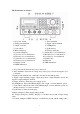
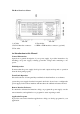
The Front Panel at a Glance 1. AC power switch 3. Earth ground terminal 5. Output on/off key 7. Control knob 9. Menu setting key 11. Current setting key 13. Store key for second function 15. Error key for second function 17. Secure key for second function 19. Clear key for second function 21. Display screen 23. REM annunciator 2. Sense terminals 4. Supply output terminals 6. Left/Right key 8. Up/Down key 10. Voltage setting key 12. Switch key for second function 14.
12. Switch key for second function (2nd): Enables the second function of other keys. 13. Store key for second function (Save): Stores the present operating states in location “0”, “1”, … “9”. 14. Recall key for second function (Recall): Recalls a previously stored operating state from location “0”, “1”,…“9”. 15. Error key for second function (Error): Checks or reads the error codes. 16. Local key for second function (Local): Returns the power supply to local mode from remote control mode. 17.
The Rear Panel at a Glance 1. AC inlet 3. RS-232 interface connector 5. Fan outlet 2. Fuse holder 4. GPIB or USB interface connector (optional) An Introduction to this Manual General Information Apart from a general description of your power supply, it provides instructions for checking your power supply, selecting power-line voltage and connecting to AC power. Initial Operation It ensures that the power supply develops its rated outputs and responds to operation from the front panel properly.
Tutorial It describes basic operation of the power supply and gives specific details on the operation and use of ARRAY 366XA power supplies. Specifications It lists the power supply’s basic specifications.
Contents Chapter 1 General Information ……………………………………...................... 11 General Information………………………………………………………………… 11 Safety Considerations………………………………………………….. ………… ...11 Description……………………………………………………………...................... 11 Installation……………………………………………………………………………12 Initial Inspection……………………………………………………….......................
Menu Setting ………………………………………………………………………24 Main Menu Description…………………………………………………………….24 Storing and Recalling………………………………………………………………24 Error Messages Display…………………………………………………………….25 Local/ Remote Operation Switch…………………………………………………..25 Protection Function…………………………………………………………………26 Abnormal Latched State Clearance…………………………………………………26 Over-Voltage…………………………………………………………………………26 Over-Temperature…………………………………………………………………….26 The Power Supply Calibration……………………………………………………….
Bus (Software) Triggering…………………………………………………………43 Immediate Triggering……………………………………………………………….44 Trigger Commands……………………………………………………………….44 System-Related Commands………………………………………………………….44 Calibration Commands……………………………………………………………….47 RS-232 Interface Commands………………………………………………………48 The SCPI Status Registers…………………………………………………………48 What is an Event Register?.......................................................................................48 What is an Enable Register?...............................
APPENDIX Error Messages …………………………………………………68 Error Messages…………………………………………………………………….68 Execution Errors…………………………………………………………………….68 Self-Test Errors……………………………………………………………………….
Chapter 1 General Information General Information This chapter provides a general description of your power supply. And it also contains instructions relate to initial inspection, selecting the power-line voltage, and connecting your power supply to AC power. Safety Considerations This power supply is a safety instrument with a protective earth terminal. The terminal must be connected to earth ground through a power source with a 3-wire ground receptacle when being connected to AC power supply.
This power supply is equipped with a liquid crystal display for displaying the output of voltage and current. A 5-digit voltage and a 5-digit current could show the actual or setting value of a selected supply simultaneously. And the liquid crystal display can show the current mode of power supply。 Connections to the power supply’s output and to chassis ground are made to binding terminals on the front panel. The Sense terminals can remotely sample the power supply’s voltage.
the over-temperature protection may take effect, depending on the input voltage and output power. A brushless fan is used to cool the power supply by drawing cool air through the two sides and exhausting the heat through the fan outlet on the rear panel. Sufficient space must be left at the rear and two sides of the cabinet for air circulation when the power supply is installed. Please remove the rubber bumpers for rack mounting. Rack Mounting The power supply could be installed in a standard 19-inch rack.
Chapter 2 Initial Operation Initial Operation This chapter mainly focuses on three basic tests which should be performed before the operation of the power supply: the preliminary checkout, the power-on checkout, and the output checkout. The preliminary checkout is to check if the power supply could run correctly.
Fuse Replacement 1 Replace the fuse Step 1: Remove the fuse-holder below AC power inlet. Step 2: Replace the fuse with the correct one that meets the requirements. Step 3: Put back the fuse holder. For 115V AC operation, 10AT fuse must be used; For 230V AC operation, 6AT fuse must be used.
Power-On Checkout The power-on test includes an automatic self-test that checks the internal microprocessors and a system self-test after the power supply is turned on, and examines the information relate to self-test process shown on the front panel. You will observe the following sequence on the display: 1. Self-test started It begins with an initial operation immediately after pressing the power switch on.
Output Checkout The output checkout is to ensure that the power supply develops its rated outputs and properly responds to various operations. Specific steps are shown as followings: Voltage Output Checkout 1. Turn on the power supply. Press the “Power-on” button, and finish the power-on checkout. Usually the power supply will go into the power-on / reset state automatically. “OFF” will be shown in the lower right corner of the display and both the output voltage and current are 0. 2. Enable the outputs.
Current Output Checkout 1. Turn on the power supply. Press “Power-on” button and finish the power-on checkout. Usually the power supply will go into the power-on / reset state automatically and the “OFF” annunciator in the lower right corner of the LCD turns on. Both the voltage value and current value are 0. 2. Connect a short across (+) and (-) output terminals of the supply with an insulated test lead. The sectional area of the shorting stub should be larger than 1.5mm2. 3. Enable the outputs.
6. Ensure that the current can be adjusted from 0A to the maximum rated value. Adjust the knob until the ammeter indicates 0A and then until the ammeter indicates the maximum rated value. If an error has been detected during the output checkout procedures, the ERROR annunciator will turn on. Refer to the related chapters in appendix for more specific error information.
Chapter 3 Front Panel Operation Front Panel Operation ` 3.1 Front Panel Operation Overview • Output on/off • Constant Voltage setting • Constant Current setting • Menu Setting • Storing and Recalling • Error Messages Display • Local/Remote Operation switch • Protection Function •Power Supply Calibration 3.2 Output on/off The output of the power supply could be switched on or off through this button.
When it is operated from remote interface, inputting the following command can enable or disable the output: OUTPUT ON/OFF. You can turn on the output by selecting ON and turn off the output by selecting OFF. 3.3 Constant Voltage Output Setting Constant voltage output is the most common output of the power supply. The voltage outputs at a constant value in constant voltage output mode, and it will not change with the load while the current will.
② Input the desired current value by pressing number keys. “Clear” key can be used to clear the wrong value to input again. ③ Press “Enter” key to confirm the current setting value. 2). Using “Left/Right” keys, knob and “Enter” key to input: ① Press “Iset” key to enter into current setting state. ② Press “Left/Right” keys to move the blinking digit to the relevant digit of the value.
② Press “Left/Right” keys to move the blinking digit to the corresponding digit of the value. ③ Increase or decrease the relevant value by turning the knob clockwise or counter clockwise, then use “Left/Right” keys to move to the next digit to modify. ④ Press “Enter” key to confirm the voltage setting value. 4. Setting the desired output current The desired current can be set directly by pressing the number keys or using “Left/Right” keys together with the knob. 1).
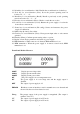
3.4 Menu Setting 3.4.1 Main Menu Description Press “Menu” key to enter into main menu, which is showed as follows: Function and Parameter Current Limit: 14.600A Voltage Limit: 35.200V Voltage Over: 36.
recall condition, the voltage and current values stored previously can be retrieved from corresponding EEPROM and set as present values. Example 1: Set voltage to 5V and current to 2A. Then turn on the power supply and save this state to the EEPROM specified by Location 1. Step Operational Details Display Information Set voltage to 5V and current to 2A. Then turn 5.000V 2.000A 1 on the power supply. 0.000W CV Press “2nd” + “Save” keys to enter into store 2 Save:0 menu.
this state as soon as it is switched on. In remote control state, all keys and knobs become invalid (except “2nd” and “Local” keys). When the power supply receives the remote command (SYST:REM) through RS232 Interface or commands through GPIB Interface, REM annunciator will be on and remote control becomes valid. In remote control state, all operations of the power source are controlled by remote controller. After receiving the command demanding the power supply to return to local control (eg.
normal range. The Power Supply Calibration Because various factors may cause the reduction of the power supply’s output precision after it has been used for a period of time, the user should calibrate the power supply’s output to make the output return to the previous precision. But it is suggested that the power should not be calibrated frequently. This section mainly introduces how to unsecure the power supply and the detailed procedures of manual calibration.
Select CV, CC or OV mode calibration by direction key. If “DEF” is selected, all calibration parameters are restored to default value. CV, CC and OV mode should be calibrated one by one, which is the correct calibration sequence. Return to calibration menu after each mode calibration is completed. Press “Clear” key to exist calibration state. 3.1 CV Mode Calibration In this mode, three voltage points: 0.5V、22V、34.5V should be calibrated. 3.1.1 Wiring + + OUTPUT KEITHLEY 2000 366XA + - SENSE 3.1.2 0.
“Enter” key to confirm. 3.1.4 34.5V Calibration Press “Enter” key to verify and then the display will show as follows: Input the value you read from KEITHLEY 2000, which is retained to four decimal places. Press “Clear” key to remove the wrong input value of current digit. Then press “Enter” key to confirm and exit to calibration menu. Now, voltage calibration is completed. 3.2 CC Mode Calibration In this mode, three current points: 0.5A、6A、9A should be calibrated. 3.2.
Input the value you read from FLUEK 45, which is retained to four decimal places. Press “Clear” key to remove the wrong input value of present digit. Then press “Enter” key to confirm. 3.2.3 6A Calibration Press “Enter” key to verify and then you will see the followings: Input the value you read from FLUEK 45, which is retained to four decimal places. Press “Clear” key to remove the wrong input value of present digit. Then press “Enter” key to confirm. 3.2.
Chapter 4 Remote Interface Reference Remote Interface Reference A detailed description of how to use the remote interface will be given in this chapter, which includes how to program the power supply through the remote interface, the commands format and matters need attention.
An Introduction to the SCPI Language SCPI (Standard Commands for Programmable Instruments) is an ASCII-based instrument command language designed for test and measurement instruments. The detailed techniques used to program the power supply over the remote interface are introduced in the following sections. SCPI commands are based on a hierarchical structure, also known as a tree system. In this system, associated commands are grouped together under a common node or root, thus forming subsystems.
Command Format Used in This Manual The format used to show commands in this manual is shown below: CURRent {|MINimum|MAXimum} The command syntax shows most commands are the mixture of upper- and lower-case letters. The upper-case letters indicate the abbreviated spelling for the command. For shorter program lines, send the abbreviated form. For better program readability, send the long form. But notice that only the complete spelling form and the upper-case letters are acceptable for the keyword.
Command Separators A colon “ :” is used to separate a command keyword from a lower-level keyword as shown below: SOURce:CURRent:TRIGgered A semicolon “ ;” is used to separate two commands within the same subsystem as shown below: SOUR:VOLT MIN;CURR MAX The following two commands have the same effect as the above command. SOUR:VOLT MIN SOUR:CURR MAX Use a colon and a semicolon to link commands from different subsystems.
You can also query the minimum or maximum value allowed with the present function as follows: CURR? MAX CURR? MIN SCPI Command Terminators A command string sent to the power supply must terminate with a character. The IEEE-488 EOI (end-or-identify) message is interpreted as a character and can be used to terminate a command string in place of a character. A followed by a is also accepted.
double quote. You can include the quote delimiter as part of the string by typing it twice without any characters in between.
[:STATe] {OFF|ON} [:STATe]? :TEXT[:DATA] :TEXT[:DATA]? :TEXT:CLEar SYSTem :BEEPer[:IMMediate] :ERRor? :VERSion? *IDN? *RST *TST? *SAV {1|2|3} *RCL {1|2|3} Calibration Commands CALibration :COUNt? :CURRent[:DATA] < numeric value > :CURRent:LEVel {MIN|MAX} :SECure:CODE :SECure:STATe {OFF|ON}, :SECure:STATe? :STRing :STRing? :VOLTage[:DATA] < numeric value > :VOLTage:LEVel {MIN|MAX} Status Reporting Commands STATus:QUEStionable [:EVENt]? :ENABle
SYSTem:ERRor? *CLS *ESE *ESE? *ESR? *OPC *OPC? *PSC {0|1} *PSC? *SRE *SRE? *STB? *WAI RS-232 Interface Commands SYSTem :LOCal :REMote :RWLock Simplified Programming Overview This chapter gives an overview of the basic commands used to program the power supply over the remote interface. Some of them are the SCPI-confirmed commands, and some are the device-specific commands. It is unnecessary to differentiate them when using ARRAY 366XA.
CURR 2.0 The two commands shown in this example has the same function as the first command shown in the above example, which shows when some individual parameter is changed, there is no need to enter the whole setting parameters as the above example, just enter some specified parameter. Reading a Query Response Only the query commands (commands that end with “?”) will instruct the power supply to send a response message, which gives the either returned values or internal instrument settings.
can set the output current value of the specified supply. For the setting range, please consult the relevant current parameters listed in the table of “Programming Ranges and Output Identifiers” section. When the voltage and current are set, the “DEF|MIN|MAX” represents the default value, the minimum value and the maximum value respectively. For example: APPLY 5.0,2.5 Set the supply to an output of 5.0V rated at 2.5A Executing the low-level commands has the same effect as this command.
Output on/off and Tracking Operation Commands Output[:STATe] {OFF|ON} This command enables or disables the outputs of the power supply. For example: OUTPUT ON OUTPUT OFF Enable the outputs Disable the outputs Output[:STATe]? This command queries the output state of the power supply and returns the corresponding values. “OFF” shows the output is disabled, and “ON” shows the output is enabled.
which is a stored value and transferred to the output terminals when a trigger occurs. A pending triggered level is not affected by subsequent CURRent commands. [SOURce:]CURRent[:LEVel]:TRIGgered[:AMPLitude]? [MIN|MAX] This query checks and returns the presently programmed triggered current level. If no triggered level is programmed, present CURRent value is returned.
[SOURce:]VOLTage[:LEVel]:TRIGgered[:AMPLitude]? [MIN|MAX] This query checks and returns the presently programmed triggered voltage level. If no triggered level is programmed, the VOLTage value is returned.
if any delay is given. 3. You can also select the trigger source from the USB, RS-232 or GPIB interface. The operation has been introduced before. Immediate Triggering 1. Select the internal immediate trigger source by sending the following command: TRIGger:SOURce IMM 2. If the IMMediate source is selected as a trigger source, once the trigger command is executed, the power supply outputs triggered output voltage and current immediately. Any delay is ignored.
messages are not sent to the display and all annunciators are disabled except the “ERROR” and “Rmt” annunciators. The display state is automatically turned on when you return to the local mode. After pressing the “Local” key to return to the local state from the remote interface, press any key except for the number keys, knobs, “Resolution”, “Clear”, ”Enter”, and “Track” keys, or “power-on/reset” key to switch to the display status automatically.
*IDN? This query command reads the power supply’s identification string. The power supply returns four fields separated by commas. The first field is the manufacturer’s name, the second field is the model number, the third field is reserved (always “0”), and the fourth field is a version code which contains three numbers.
Calibration Commands CALibration:COUNt? This command queries the power supply to determine the number of times it has been calibrated. CALibration:CURRent[:DATA] This command can only be used after calibration is unsecured. It enters a current value of a selected output that you obtained by reading an external meter. You must first select a calibration level (CAL:CURR:LEV) for the value being entered.
are then stored in internal memory. CALibration:VOLTage:LEVel {MINimum | MAXimum} Before using this command, you must select the output which is to be calibrated by INSTrument command. This command can only be used after calibration is unsecured. It sets the power supply to a calibration point that is entered with CALibration:VOLTage[:DATA] command. During calibration, two calibration points must be entered and the low-end point (MIN) must be selected first.
not clear bits in event registers. Querying an event register returns a decimal value which corresponds to the binary-weighted sum of all bits set in the register. What is an Enable Register? An enable register defines which bits in the corresponding event register are logically ORed together to form a single summary bit. Enable registers are both readable and writable. Querying an enable register will not clear it.
QUEStionable Status Event Registers Enable Registers VOLTage 0 CURRent 1 Not used Not used TEMPerature Output Buffer 4 Not used Not used “OR” Not used Not used OVERvoltage 9 Not used Not used Not used Not used Not used Status Byte Not used Event Registers STAT:QUES? STAT:QUES:ENAB STAT:QUES:ENAB? Enable Registers Not used Not used Standard Event Event Registers Operation Complete OPC Not used Enable Registers 0 Not used Query Error QYE 2 Device Depenent Error Execution Error
Bit Decimal Value 0(Voltage) 1 1(Current) 2 2-3(Not used) 0 The power supply is in constant voltage mode. The power supply is in constant voltage mode. Always set to 0. 4(Over-temperature) 16 The fan has a fault condition. 5-8(Not used) 0 Always set to 0. 9(Over Voltage) 512 10-15(Not used) 0 Definition The power supply over-voltage state. Always set to 0. is in The questionable status event register is cleared when: 1. You execute the *CLS (clear status) command. 2.
Bit Definitions - Standard Event Register Bit Decimal Value 0 OPC 1 1 not used 0 2 QYE 4 3 DDE 8 4 EXE 16 5 CME 32 6 not used 0 7 PON 128 Definition Operation Complete. All commands prior to and including an *OPC command have been executed. Always set to 0. Query Error. The power supply tried to read the output buffer but it was empty. Or, new command line was received before a previous query had been read. Or, both the input and output buffers are full. Device Error.
The Status Byte Register The status byte summary register reports conditions from the other status registers. Query data that is waiting in the power supply’s output buffer is immediately reported through the “Message Available” bit (bit 4) of status byte register. Bits in the summary register are not latched. Clearing an event register will clear the corresponding bits in the status byte summary register.
queue. The additional errors will not be stored. 1. Errors are stored and retrieved in first-in-first-out (FIFO) order. The first error returned is the first error that was stored. When you have read all errors from the queue, the “ERROR” annunciator turns off. 2. If more than 20 errors have occurred, the last error stored in the queue (the most recent error) is replaced with -350, “Too many errors”. No additional errors are stored until you read or remove errors from the queue.
*OPC This command sets the “Operation Complete” bit (bit 0) of the standard event register after the command is executed. *PSC { 0 | 1 } (Power-on status clear.) This command clears the status byte and the standard event register enable masks when power is turned on (*PSC 1). When *PSC 0 is in effect, the status byte and standard event register enable masks are not cleared when power is turned on. *PSC? This command queries the power-on status clear setting.
DISPlay [:WINDow][:STATe] {OFF|ON} [:WINDow][:STATe]? [:WINDow]:TEXT[:DATA] [:WINDow]:TEXT[:DATA]? [:WINDow]:TEXT:CLEar MEASure [:SCALar]:CURRent[:DC]? [:SCALar] :VOLTage[:DC]? OUTPUT [:STATe] {OFF/ON} [:STATE]? [SOURce:] CURRent[:LEVel][:IMMediate][:AMPLitude] {|MIN|MAX} CURRent[:LEVel][:IMMediate][:AMPLitude]? [MIN|MAX] CURRent[:LEVel]:TRIGgered[:AMPLitude] {|MIN|MAX} CURRent[:LEVel]:TRIGgered[:AMPLitude]?[MIN|MAX] VOLTage[:LEVel][:IMMediate][:AMPLitude] {|MIN|M
Device-Specific Commands The following commands are specific to the ARRAY 366XA power supply. However, these commands are designed with the SCPI Command in mind and they follow all of the syntax rules defined by the standard command.
Chapter 5 Application Programs Application Programs RS-232 Operation Using QuickBACSIC The following example shows how to send command instruction and receive command responses over the RS-232 interface using QuickBASIC. This program has been tested and can be used directly.
Chapter 6 Tutorial Tutorial The ARRAY 366XA is a high performance instrument capable of delivering clean dc power. But to take full advantage of the performance characteristics designed into the power supply, certain basic precautions must be observed when it is connected for use on the lab bench or as a controlled power supply. This chapter gives specific details on the operation of the ARRAY 366XA power supply.
Figure below shows the operating modes of the three outputs of the power supply. The operating point of one supply will be either above or below the line RL = RC. This line represents a load where the output voltage and the output current are equal to the voltage and current setting. When the load RL is greater than RC, the output voltage will dominate since the current will be less then the current setting. The power supply is said to be in constant-voltage mode.
And the noise across the output terminals is of very low value in the ARRAY 366XA. The noise from the terminals to earth ground can be a problem for very sensitive circuitry that is referenced to earth ground. When a circuit is referenced to earth ground, a low level line-related AC current will flow from the output terminals to earth ground. Any impedance to earth ground will create a voltage drop equal to the current flow multiplied by the impedance.
Considerations During the operation of the power supply, various problems may occur because of the difference in connected loads, which will be introduced as follow respectively. Capacitive Load In most cases, the power supply will be stable for capacitive load of any size. Load with large capacitor may cause ringing in the power supply’s transient response. It is possible that certain combinations of load will result in output instability.
Series operation of two or more power supplies can obtain a higher voltage output than that is available from a single supply. Series connected power supplies can be operated with one load across power supplies. The power supply has a related internal protection function so that if operated in series with other power supplies, damage will not occur when the load is short-circuited or the series-wound power supply are not turned on simultaneously.
Chapter 7 Specifications Specifications The performance specifications of ARRAY 366XA are listed in this chapter in details (Specifications are warranted in the temperature range of 25±2℃ with a resistive load.). Please consult the relevant data in actual use.
Current Readback Resolution Voltage Current Meter Resolution Voltage Current 1mA 1mA 1mA 1mV 1mA 2mV 1mA 4mV 1mA 1mV 1mA 2mV 1mA 4mV 1mA Transient Response Time Less than 1ms for output to recover to within 100 mV following a change in output current from full load to half load or vice versa Command Processing Time Programming Commands: Maximum time for output to change after receiving APPLy and SOURce commands: <50msec Readback Command: Maximum time to readback output MEASure? command: <100msec T
Voltage Programming Speed Maximum time required for output voltage to settle within 1% of its total excursion (for resistive load). Command processing time is excluded.
APPENDIX Error Messages Error Messages When the front-panel ERROR annunciator turns on, and the power supply generates a short beep, one or more command syntax or hardware errors have been detected. A record of up to 20 errors is stored in the power supply’s memory. Errors are stored and retrieved in first-in-first-out (FIFO) order. The first error returned is the first error that was stored. When you have read or cleared all errors from the queue, the ERROR annunciator turns off automatically.
colon, semicolon, or blank space with a comma or you may have replaced a comma with a blank space. Example: TRIG:SOUR,BUS or APPL P6V 1.0 1.0 -104 Data type error The wrong parameter type was found in the command string. You may have specified a number where a string was expected, or vice versa. -108 Parameter not allowed More parameters were received than expected for the command. You may have entered an extra parameter, or you added a parameter to a command that does not accept a parameter.
-138 Suffix not allowed A suffix was received following a numeric parameter which does not accept a suffix. Example: STAT:QUES:ENAB 18 SEC (SEC is not a valid suffix). -144 Character data too long The character data element contained too many characters. -151 Invalid string data An invalid character string was received. Check if you have enclosed the character string in single or double quotes.
output buffer is cleared when power has been off, or after a *RST (reset) command has been executed. -420 Query UNTERMINATED The power supply was addressed to talk (i.e., to send data over the interface) but a command has not been received which sends data to the output buffer. For example, you may have executed an APPLy command (which does not generate data) and then attempted an ENTER statement to read data from the remote interface.
Calibration Errors Code Explanation 702 Cal secured The calibration is secured. 703 Invalid secure code An invalid calibration security code was received when attempting to unsecure or secure the power supply. You must use the same security code to unsecure the power supply as what was used to secure it, and vice versa. The security code may contain up to 12 alphanumeric characters. 704 Secure code too long A security code was received which contained more than 12 characters.
758 Cal checksum failed, store/recall data in location 8 759 Cal checksum failed, store/recall data in location 9 73