Exhibit 6: User’s Manual External Radio Frequency Power Amplifier OM4000HF Model 4000HF Array Solutions 2611 North Beltline Rd Suite 109 Sunnyvale, Texas 75182 USA Tel: 214 954 7140 fax: 214 954 7142 E-mail: info@arraysolutions.
TABLE OF CONTENTS 1. GENERAL INFORMATION 1.1. Introduction ……………………………………………………………….. 4 1.2. Specification …………………………………………………………….... 4 1.2.1. Parameters …………………………………………………………………. 4 1.2.2. Protection Circuits ………………………………………………………… 4 1.2.3. Indicators ………………………………………………………………….. 5 2. SAFETY INSTRUCTIONS ……………………………………………… 5 3. GENERAL DESCRIPTION ………………………………………………. 6 3.1. HF part ……………………………………………………………………. 6 3.2. Power Supply …………………………………………………………….. 7 3.3.
7. APPENDIX ……………………………………………………………... 17 7.1. Block Diagram of OM4000 HF Power Amplifier ……………...………...
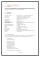
1. GENERAL INFORMATION 1.1. Introduction The OM Power model OM4000 HF is a manual tuning power amplifier, designed for use on all short wave amateur bands from 1.8 to 29.7 MHz (including WARC bands) and all modes. . It is equipped with a two pieces of ceramic tetrode FU728F. 1.2. Specification 1.2.1. Parameters Frequency Coverage Power Output Input Power Amateur Bands 1.8 – 29.
1.2.3. Indicators There are couples of LED and bar graph indicators visible on the front panel to inform you about value of some parameters or operation status: Bar graph indicators Power output - 50 LED Reflected power – 20 LED Current at screen Ig2 – 10 LED Anode voltage, anode current, tuning – 30 LED LED Indicators Current at control grid (Ig1 – 2 LED) WAIT – preheating of tube (180 sec) STBY – standby OPR – operation condition FAULT – failure, switching off for abt. 2 sec 2.
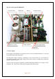
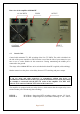
WARNING! Before opening the upper lid of the amplifier make sure that power supply has been disconnected AT LEAST 5 minutes, allowing the electrolytic capacitors to discharge fully.
Top view on the opened OM4000 HF Tetrode FU728F Output Pi-L Circuit PWR meter Blower Tuning capacitor Switch-on board Power supply board Subpanel 3.2. Power Supply Power supply of the amplifier is comprised of two of 3 kVA toroidal transformers. A soft start is provided using relays and resistors. The high anode voltage is made by combining 8 x 420 V (total 3360V) @ 2.5A. Each has its own rectifier and filter.
3.3. Safety Devices Control and monitoring circuits ensure control and safety during malfunctions of the PA. These are on the Control board, which is located on the chassis subpanel. 4. INSTALLATION NOTE Read this chapter carefully prior you will start installation. Before unpacking inspect shipping woody container first, if it is not damaged. Keep all of packing parts for possible future shipment. Check unpacked power amplifier.
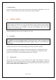
Rear view of the amplifier OM4000 HF AC SOCKETS FUSES CONTROL 4.3. OUTPUT INPUT Control Cable Control cable maintains TX / RX switching of the PA (TX GND). The cable is shielded. On the side of the power amplifier a CINCH-socket is used. On the side of your transceiver you have to use a socket suitable for this transceiver. During transmitting the middle pin is connected to the ground. The relays of the OM4000 HF have to be switched earlier than HF is applied (cold switching).
4.4. Mains Supply CAUTION Be sure you got PA with properly terminated mains cables, corresponding with your power system’s outlet. If not, contact your dealer. In such a case you should make the necessary changes using a licensed electrician. WARNING! Be sure that your power system is correctly wired and properly rated! To use adequately sized and connected grounding system is also very important. 4.5.
CAUTION Do not turn PA on for at least 2 hours after unpacking it and locating in its operating location. Especially when amplifier is moved from a cold place to a warm one because not visible condensation may develop, and this could result in damage to the high voltage circuits of the PA. CAUTION Never try to change antenna output during a transmission to avoid warranty loss. NOTE When you decide to have a short operating break, place the amplifier in the standby mode rather than switch it off. 5.1.
In STBY, if WAIT-LED is on or the amplifier is OFF, the amplifier is in bypass-mode and your transceiver is directly connected to the antenna. Maximum allowed power in bypass mode is 200 Watts! RF OUTPUT Bar graph – shows output power . REFLECTED POWER Bar graph – shows reflected power from the antenna. Maximum level is 350W otherwise amplifier switches to STANDBY mode. Ig2 Bar graph – measures the current of the second grid from -80mA to +120mA.
1. Set the multimeter switch to the HV position 2. Set the OPR/STBY switch to the STBY position 3. Press the ON button The amplifier is prepared for operation with the following automatic steps: • • • • The toroidal transformers are switched on step by step. The cooling blower for the final tube is switched on. The multi-meter bar graph measures the high voltage; the normal value is 3.3 kV The WAIT LED lights up CAUTION After switching on, please confirm that the blower is operating properly.
Band Tune Load 1.8 3.5 7 10 14 18 21 24 28 30 65 50 60 70 70 30 45 15 50 55 85 25 40 45 65 60 75 8. Set TUNE knob in such a way, that the TUNE-LED lights up maximum left. 9. Set LOAD in such a way, that the TUNE LED on the TUNE scale lights up under the “V” sign. If it is possible to obtain the LOAD in 2 positions, set the position that is more to the right. 10. Repeat tuning several times according to 8 and 9, power output should be abt. 400W 11.
6. 6.1. MAINTENANCE Indication of fault conditions OM4000 HF has the following indication LED on the front panel: GRID MIN GRID MAX HV IP FAULT OPR STBY WAIT - Indication of first gird current Max.
Dealer in USA: Array Solutions 2611 North Belt Line Road Suite # 109 Sunnyvale, TX 75182 Tel: (214)954-7140 Email: sales@arraysolutions.com 6.2. Fuse Replacemeent The user is allowed to change mains fuses (6,3 x 32mm), accesible from the rear panel, only. In the case of interrupted fuse (fuses) inside the power amplifier, contact your dealer, please. 6.3. Tube Replacement In the case of vacuum tube damaging, contact the manufacturer or your dealer for ordering new one.
Page 17 of 17 2 2 2 2 1 1 1 1 AC2 K1 K3 2 1 TR1 K2 K5 TR2 AC14V SW ON BOARD K7 K4 AC1 T sensor 1 2 2 1 2 Blower Ext.bl.