
User's Manual

Page 12 of 17
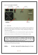
In STBY, if WAIT-LED is on or the amplifier is OFF, the amplifier
is in bypass-mode and your transceiver is directly connected to the
antenna. Maximum allowed power in bypass mode is 200 Watts!
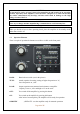
RF OUTPUT Bar graph – shows output power .
REFLECTED POWER Bar graph – shows reflected power from the antenna.
Maximum level is 350W otherwise amplifier switches to
STANDBY mode.
Ig2 Bar graph – measures the current of the second grid from -80mA to
+120mA.
HV/IP/TUNE Bar graph – measure the anode voltage, anode currency or tuning of PA.
5.2. Tuning of Power Amplifier
The OM4000 HF amplifier is operated in class AB. Thus it’s possible to obtain a maximum
output power at excellent linearity. For this purpose the amplifier has to be tuned carefully.
WARNING!
Before starting tuning you have to check if the right antenna or a 50 Ohms load
resistance is connected at the antenna output!
CAUTION
The operation of a mistuned PA will cause malfunctions, the increase of grid current
(the GRID-MAX-LED will light up) and problems with TVI/BCI.
CAUTION
The grid-current is shown with 2 LED diodes. It’s normal if the green LED is flashing or
may be shining a little bit during peak operation. If you overload the amplifier the
output power increases the grid current at very small rates and the red GRID-MAX-
LED is shining and the safety devices switch the PA to STBY. You must decrease the
input power.
CAUTION
In SSB mode you will have good output power if the green LED lights up a bit. The
current of screen grid is measured and shown in a Bar graph Indicator. The amplifier
has to be tuned in such a way that the current is between - 80 mA to +80 mA. At
currents beyond these values the operating point will be shifted and IM-products will be
rapidly increased. If a value of + 100mA is exceeded, the safety devices will switch the
amplifier to STBY mode.