
User's Manual

Page 8 of 17
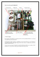
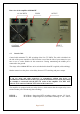
3.3. Safety Devices
Control and monitoring circuits ensure control and safety during malfunctions of the PA.
These are on the Control board, which is located on the chassis subpanel.
4. INSTALLATION
NOTE
Read this chapter carefully prior you will start installation. Before unpacking inspect shipping
woody container first, if it is not damaged. Keep all of packing parts for possible future
shipment. Check unpacked power amplifier. If you find some damaging, contact your dealer
immediately to keep full warranty.
During installation go step by step according to next parts.
4.1. Grounding
CAUTION
The amplifier has to be grounded properly! Connect the screw on the rear panel of the
amplifier to your local grounding system with a copper cable, use a cross-section of 4
mm
2
at least.
Connect your transceiver to the same grounding system of your shack carefully!
Use minimum length cables and make certain that the connections are both physically and
electrically sound. With poor grounding, you may risk damaging your equipment, having
problems with TVI/BCI or your transmitted signal may be distorted.
4.2. Coaxial Cable
The output of the transceiver is to be connected to the input of the amplifier via RG58 or
similar cable. For the connection between the power amplifier and the antenna, RG213 or
similar coaxial cable suited for high power is recommended. Both the INPUT and OUTPUT
SO-239 sockets with Teflon insulation is used.