
User's Manual
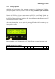
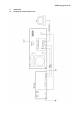
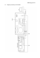

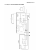
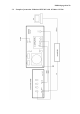
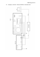
Exhibit 6 page 23 of 33
6. MAINTENANCE
6.1. Indication of fault conditions
OM2500A has the following indication LED on the front panel:
GRID MIN - indication of first gird current
GRID MAX - max. First grid current exceeded
HV - measuring of anode voltage by bar graph
IP - measuring of anode currency by bar graph
FAULT - fault
OPR - amplifier in operation mode
STBY - amplifier in standby mode
WAIT - heating of tube after switching on the amplifier
NOTE
Should a fault condition appear during the tuning or operation of the amplifier the safety
circuits of OM3500A will react. The amplifier will be turned to STBY mode. After approx. 1
sec the control circuits will switch the amplifier back to OPR.
CAUTION
If the fault will repeat 3 times after each other the control circuits will turn the amplifier
to STBY. Bringing the amplifier to OPR is enabled by using the OPR/STBY switch only.
After reaction of safety circuits the FAULT LED will be lit up for approx. 5 sec, depending
on the nature of the fault.
Flashing LED signalizes:
IP - anode currency exceeded
HV - low anode voltage
FAULT - reflected output exceeded
GRID MAX - first grid currency exceeded
- screen grid currency exceeded
GRID MAX + HV - maximum load power exceeded
GRID MAX + IP - zero output power during tuning
HV + IP - tuning fault, incorrect tuning of the Pi-L output circuit
In case your OM2500A amplifier is not working correctly, please contact the
manufacturer or your dealer.
Manufacturer’s contacts: OM POWER, s.r.o.
930 30 Báč 126
SLOVAKIA
Email: ompower@nextra.sk