
User's Manual
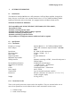
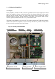
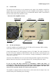
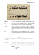

Exhibit 6 page 9 of 33
4.2. Coaxial Cable
The output of the transceiver is to be connected to the input of the amplifier via RG58 or
similar cable. For the connection between the power amplifier and the antenna, RG213 or
similar coaxial cable suited for high power is recommended. Both the INPUT and OUTPUT
SO-239 sockets with Teflon insulation is used.
Rear view of the amplifier OM2500A
MAINS Cable Fuses OUTPUT
REMOTE I / O Interface INPUT
4.3. I/O Box and Interface
Control of Amplifier and communication with TCVR as well as Antennas / BPF switching
can be done via the rear panel I/O Interface.
Control cable maintains TX / RX switching of the PA (TX GND). The cable is shielded. On
the side of the power amplifier a CINCH-socket is used. On the side of your transceiver you
have to use a socket suitable for this transceiver. During transmitting the middle pin is
connected to the ground.
The relays of the OM2500A have to be switched earlier than HF is applied (cold switching).
Modern transceivers they have a time delay between PTT switching and power output.
CAUTION
If you are using and older transceiver or transmitters without time delay, we
recommend to connect the PA in such a way that the transmit/receive switch (foot switch
for example) is connected with the KEY IN socket of the amplifier. The KEY OUT
socket is to be connected with the PTT socket at the transceiver.
The amplifier is equipped with two safety devices, which ensure that the output relay is not
switched under power mistakenly (hot switching).