HD-IVS for ARRICAM LT K2.47060.0 Instruction Manual Attention: This is only a preliminary version. The content may be changed without notice. ARRI assumes no responsibility for errors in this manual. A final version will be delivered as soon as possible. Preliminary Version February 2010 K5.40829.
1 2 Quick Reference................................ ................................ ................................ 3 Safety Instructions and Legal Disclaimer ................................ ......................... 5 2.1 Safety Instructions ................................ ................................ .................... 5 2.2 Legal Disclaimer ................................ ................................ ...................... 7 2.3 Declaration of Conformity ................................ .
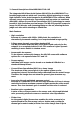
1 Quick Reference GGC ON/OFF GGC Iris value setting HD-Link mode Switch - Check/Hide menu and ON/OFF HD-Link speed USB Increase gain, blue channel, GGC iris value, cursor up or move inserted window up É Video with Graphic Overlay HD-SDI Increase format numbers, values, red channel or go into sub menu È Clean video Decrease format numbers, values, red channel or go into sub menu HD-IVS Decrease gain, blue channel, GGC iris value, cursor down or move inserted window down Switchable output HD-IVS
MENU EDIT TEXT 4
2 Safety Instructions and Legal Disclaimer 2.1 Safety Instructions Please always follow these instructions to help ensure against injury to yourself and damage to the system or other objects. This safety information is additional to the product-specific operating instructions in general and must be strictly observed for safety reasons. Furthermore, you are obliged to incorporate and observe sufficient safety measures of your own.
• Operate the system using only the type of power source indicated in the manual. Unplug the power cord by gripping the power plug, not the cord. • Never insert objects of any kind into any part of the system through openings, as the objects may touch dangerous voltage points or shortcircuit connections. This could cause fire or electrical shock.
Product Identification When ordering parts or accessories, or if any questions should arise, please advise your type of product and serial number. 2.2 Legal Disclaimer Before using the products described in this manual, be sure to read and understand all relevant instructions. The HD-IVS System is only available for commercial customers. By utilization the customer agrees, that the ARRI HD-IVS or other components of the system are only deployed for commercial use.
assembly or use of our products, or any other damages or injury of persons and so on or under any other legal theory. In the case one or all of the forgoing clauses are not allowed by applicable law, the fullest extent permissible clauses by applicable law are validated. ARRI is a registered trademark of Arnold & Richter Cine Technik GmbH & Co Betriebs KG. 2.
3 General Description of the ARRICAM LT HD -IVS The Integrated HD Video-Assist System (HD-IVS) for the ARRICAM LT is a breakthrough product, which uses innovative digital technology to create high definition video assist images for the ARRICAM LT film cameras. Wide dynamic range, excellent color reproduction and low noise are combined with ARRI’s unique Ground Glass Cancellation (GGC) technology to create beautiful, high resolution preview images.
maximum speed; the video image is always taken at the ideal position of the mirror shutter. Flicker free can be switched off to bypass the digital frame store and to have minimal delay in the video system. • Full white balance control Indoor,-outdoor, automatic, manual and one –push white for an automatic detection of white charts. • Store and recall settings All settings can be stored and recalled.
images. This clearly shows the difference between the images, e.g. during stop effect shots. • Automatic and manual gain control The gain is controlled automatically to its best value but can also be set manually. • Mini monitor connector: The HD-IVS has a BNC connector for an HD-IVS Mini Monitor. The mini monitor needs to get power on a separate power cable. 3.1 Order Numbers ARRICAM LT HD-IVS order number: K2.47060.0 HD-IVS for ARRICAM LT K2.64200.0 K2.64201.
This operation should be carried out only by an experienced technician. Use appropriate care to avoid electro static discharge. Do not touch optical surfaces and do not use force. If you feel uncomfortable in changing the IVS Lens, please don’t hesitate to consult one of the authorized ARRI Service Centers. A 3 mm, a 2mm and a 1,5mm hex key, and a pair of tweezers are used.
Don’t pull on the flexible PCB. Disconnect the connector → Photo by using a pair of tweezers. Turn the focus screw S1 → Photo counter clockwise by using a 1.5 mm hex key until the lens comes loose (as shown on the next image) and pull it out carefully. Make sure the flexible PCB and its connector slips through the housing, without being pulled.
The focus ring has to be in the correct position, to reassemble the lens: Turn the focus ring as shown in the image until it reaches the end stop – then turn it back a quarter of a revolution to loosen it. → Photo Make sure that the small pin on the lens fits the groove in the optics assembly. → Photo Carefully feed the connector and the flexible PCB through the housing. → Photo Push the lens gently against IVS and turn the focus screw S1 clockwise by using a 1.5 mm hex key until the lens gets pulled in.
Make sure to mount the correct Lens Type Marker on the HD-IVS, so that it is visible from the outside which type of lens is used. The information 4:3 and 16:9 are each printed on one side of the plate. To change, unscrew the two screws S1 and S2 using a 1,5mm hex key, and screw the correct side of the plate with the two screws back on again.
3.3 Changing the IVS Lens The HD IVS allows the use of two different IVS prime lenses as a video assist lens. The 4:3 IVS lens is optimized for taller aspect ratios such as 4:3 or anamorphic formats. The full 4:3 ground glass image will be displayed on 1440 x 1080 pixels on the HD monitor, leaving black vertical bars to the left and right of the image (“pillar box”). These black bars optionally display metadata or the OSD menu. The 16:9 IVS lens is optimized for aspect ratios of 16:9 or wider.
A 3 mm, a 2 mm and a 1.5 mm hex key, and a pair of tweezers are used. To take the cover (shown on the next image) off the HDIVS-LT, loosen the captive screws S1 and S2 with a 3 mm hex key → Photo The cover will drop off. To lift the optics assembly off the video assist, loosen the captive screws S3 to S6 with a 2 mm hex key as shown on the previous image. → Photo Don’t pull on the flexible PCB. Disconnect the connector → Photo by using a pair of tweezers.
Turn the focus screw S1 → Photo counter clockwise by using a 1.5 mm hex key until the lens comes loose (as shown on the next image) and pull it out carefully. Make sure the flexible PCB and its connector slips through the housing, without being pulled. → Photo The focus ring has to be in the correct position, to reassemble the lens: Turn the focus ring as shown in the image until it reaches the end stop – then turn it back a quarter of a revolution to loosen it.
Carefully feed the connector and the flexible PCB through the housing. → Photo Push the lens gently against IVS and turn the focus screw S1 clockwise by using a 1.5 mm hex key until the lens gets pulled in. → Photo Plug in the connector and reassemble the optics assembly in reverse order. Make sure to mount the correct Lens Type Marker on the HD-IVS, so that it is visible from the outside which type of lens is used. The information 4:3 and 16:9 are each printed on one side of the plate.
3.4 Installation of the HD IVS onto the ARRICAM LT A 3 mm and a 1.5 mm hex key are used. First remove the handle after loosening the captive screws S1 and S2 with a 3 mm hex key. → Photo Loosen the captive screw S3 with a 3 mm hex key and remove the view finder cover. → Photo Take the cover off the HD IVS. To do so loosen the screws S1 and S2 with a 3 mm hex key. The cover, which is located on the other side, will fall off.
Mount the HD IVS onto the ARRICAM LT view finder as shown → Photo. Use a 3 mm hex key to tighten screws S1 and S2. Now the handle can be mounted back on by securing the screws S1 and S2 with a 3 mm hex key. 3.5 Outputs The HD-IVS has three HD-SDI outputs, one for video with text and graphic overlay and one for video without text and graphic and one output switchable between the two. The output is HD-SDI with 4:2:2 color sampling. The HD-Link speed is selectable between 23.976, 24, 25, 29.
3.7 HD-SDI Output with Graphic Overlay In the output HD-SDI with graphic overlay, marked with the É symbol → Photo, additional data such as frame lines, camera status information, camera system information and a user text line are inserted. The outputs are standard BNC sockets for 75 Ω terminated video signals. All outputs can be used simultaneously. In order to ensure appropriate image quality, make sure to use cables which are capable to handle the 1.5 GB/s data rate of the HD-SDI signal.
In order to ensure appropriate image quality, make sure to use cables which are capable to handle the 1.5 GB/s data rate of the HD-SDI signal. We recommend cables according to RG 59 standard. As there is only one mini monitor connector, it is possible to switch between signals without graphic overlay and signals with graphic overlay on this output. To switch between normal video and video with data on the mini monitor output, use the on-screen program mode.
4 Standard Video Controls The HD-IVS can be used like a standard video system if no inserter features are used. Note: All currently used settings are stored, even if the HD-IVS or the camera is switched off. After restarting the HD-IVS the settings are unchanged, except for the image stored mode, which will always come up in live mode and color bars, which will not be visible after power up. 4.
4.2 Iris The HD-IVS has an iris inside the IVS lens. It is automated in such a way, that the CCD sensor receives just the right amount of light in order not to be overexposed. By this, the electronic amplification of the image (gain) can be minimized. This avoids noise in the video image. Only a relatively small portion of the light which passes through the film camera’s lens reached the CCD-Chip of the video assist, as the light is shared between the view finder, the CCD-Chip and the film.
All settings can be made by using a 1.5 mm hex key, which is delivered with the HD-IVS. Do not use force! Screw S 1 Ò moves the video image on the monitor horizontally. → Photo Screw S 2 rotates the image around a point which is located in the middle of the right image border. → Photo Screw S 3 rotates the image around a point which is located in the middle of the left image border → Photo Therefore, the screw S 2 and screw S 3 as an adjustment for rotation. 4.
4.5 White Balance (WB) The HD-IVS offers a choice for: • White Balance between an automatic control (AWB) and manual settings. • a fixed setting of indoor (IND) • a fixed setting for outdoor (OTD) • the so called one-push white procedure which takes a white object such as a piece of paper as a white reference and sets color balance accordingly. • a full manual control of white balance (MAN). White balance can be adjusted in two different ways.
If automatic White Balance (AWB) is selected, the HD-IVS will automatically set White Balance. For this no manual steps are necessary → Photo. If indoor (IND) is selected → Photo white balance is optimized for tungsten lighting with 3200 K. The outdoor (OTD) setting → Photo optimizes the white balance for daylight with 5600 K. The LEDs on the keypad will follow the changes which are made in the menu and vice versa, if the setting is changed via the keypad, the onscreen menu will follow.
If white balance is on manual, the display will change. Dashes will appear left of ONE PUSH WHITE; RED and BLUE indicating that the ONE PUSH WHITE procedure can be activated or red and blue saturation of the video image can now be changed. One-push white Note: ONE PUSH WHITE is only available, when white balance is set to manual. If manual WHITE BALANCE is set to MAN, it is possible to use the one push white facility or to adjust the red and blue saturation of the video image manually.
Manual White Balance red increase/decrease Note: Manual white balance red increase/decrease is only available if WHITE BALANCE control is on manual. If WHITE BALANCE is on MAN, it is possible to adjust the red and blue saturation of the video image manually. Move the cursor by using the keys Ê and Ë to the line – RED → Photo. Pressing the key Í will increase the red in the video image; the key Ì will decrease it. The range for this is from 0 (lowest) to 63 (highest).
this is from 0 (lowest) to 63 (highest). If the key Í or Ì is pressed briefly, the value is changes by one increment, if the keys are pressed longer, the value will continue to change. The LED in the keyboard will follow the changes which are made in the menu and vice versa, if this setting is changed via the keyboard, the onscreen menu will follow. 4.6 Gain Control The HD-IVS can change the brightness of the video image electronically. This gain control can be automatic or manual.
4.6.2 Using the On-Screen Menu Please see chapter 5 Inserter Facilities for basics on the On-Screen display. Parallel to the control via the keyboard, the manual gain control can also be programmed via the on-screen menu. Manual gain control can be switched on or off. If it is on, specific values can be set between 0 (low gain) and 63 (high gain). Enter the main menu by pressing the Enter/Insert key Ñ for more than three seconds. Go to sub menu WB/GAIN/BARS → Photo.
Manual Gain increase/decrease Note: MANUAL GAIN increase/decrease is only available if manual gain control is on. Move the cursor by using keys Ê and Ë to the line – VALUE → Photo. Pressing the key Í will increase the gain; the key Ì will decrease it. The range for this is form 0 (lowest gain) to 63 (highest gain). If the keys Í or Ì are pressed briefly, the value changes by one increment, if the keys are pressed longer, the value will continue to change.
However, it is possible to select which format markings are displayed via the keyboard. The FORMAT MARKING selection is only available, when the WHITE BALANCE manual mode is not active (when the WB MAN LED is not flashing). If WHITE BALANCE manual mode is active, please wait for more than 5 seconds without pressing any key to leave this mode. The key Í will switch from OFF, 1, 2 to 1&2. The key Ì will switch in opposite order. → Photo 4.7.
4.8 Ground Glass Cancellation (GGC) On/Off All video assists capture the image they see on the ground glass of the film camera; this ensures that the framing and the impression of depth of field are identical between the film and the video assist image. The ground glass is an integral part of the optical viewfinder, a feature of 35 mm film cameras much loved by camera operators. Unfortunately, the ground glass also creates a visible texture on traditional video assists.
4.8.2 Using the On-Screen Menu Although all settings are done on the HDIVS, please always check all the changes on the connected monitor as well. Parallel to the control via keyboard, the GGC software can be switched on and off via the on screen menu. Enter the main menu by pressing the Enter/Insert key Ñ for more than three seconds. Go to sub menu CCG. Move the cursor by using the keys Ê and Ë to the line – GGC → Photo. Pressing the key Í or Ì will switch GGC off and on.
4.9.1 Using the Keyboard Note: The setup of the GGC can be done only in the on-screen menu as descirbed in chapter 5.10 CCG Control If this mode can not be selected, please check the setting of IRIS VALUE BY. See chapter 5.10.2 Iris. Changing of GGC value for the iris is only necessary if lenses without the Lens Data System are used. Press the key briefly (less than 1.5 seconds). The LED next to GGC will blink, showing that it is now possible to change the GGC value for iris.
Using the on-screen menu Check all settings on the connected monitor. Parallel to the control via the keyboard, the GGC value for the iris can be switched on and off via the on screen menu. Note: The IRIS setting is only available if lenses without the Lens Data System are used as described in the chapter 5.10.2 Iris. Enter the main menu by pressing the Enter/Insert key Ñ for more than three seconds. Go to sub menu CCG. Move the cursor by using keys Ê and Ë to the line – IRIS → Photo.
4.10 HD Link Speed The HD-IVS allows to set the HD-link speed to 23.976 FPS, 24 FPS, 25 FPS, 29.97 FPS and 30 FPS. Please make sure that the selected HD link speed is supported by your recording device and monitor. 4.10.1 Using the Keyboard Pressing the key will switch from 23.976 FPS to 30 FPS link speeds. → Photo Please note that the control via the keyboard is possible, even if the monitor does not support the selected link speed. Therefore control via the keyboard is always possible.
4.11 HD-Link Mode The HD-IVS allows to use either progressive, interlaced or segmented image transfer mode. Please make sure that the selected HD link speed is supported by your recording device and monitor. 4.11.1 Using the Keyboard Pressing key will witch from interlaced (I) to segmented (S) and to progressive (P) link mode. → Photo Please note that the control via the keyboard is possible, even if the monitor does not support the selected link speed.
4.12 Storing a Video Image to Internal Memory The HD-IVS can store an image, display it or overlay it against the live image in front of the camera to compare both images. Although the functions to display a stored image and to compare a stored image against a live image are only available in the on-screen program mode, it is possible to store an image any time using the Enter/Insert key Ñ. 4.12.1 Using the Keyboard Pressing the Enter/Insert key Ñ briefly (less than 1.
5 Inserter Facilities In addition to the usual video assist functions, the HD-IVS offers a variety of inserter facilities. There are three different groups of information: • Format markings Format markings, which are inserted electronically, are often more visible than format markings on the ground glass or on the ARRIGLOW.
Once the on-screen display is activated by pressing the Enter and Insert key Ñ for more than three seconds, the following procedure is used to select and set all functions within the main menu and the sub menus: Pressing the key Ê or Ë will move the cursor up or down. Pressing the key Í or Ì activates sub menus. Within sub menus the cursor can be moved up and down again by pressing the key Ê or Ë. The keys Í or Ì will now change settings (e. g.
5.2 Main Menu The inserter’s main menu is displayed on the monitor screen when the onscreen programming is activated by pressing the Enter/Insert key Ñ for more than three seconds. An illuminated LED indicates that the on-screen programming is activated. Note: Pressing the Enter/Insert key Ñ for more than three seconds will cause the system to exit the on-screen programming mode completely, regardless of which menu is activated, with the exception of the positioning mode.
5.3 Load/Store Menu The HD-IVS can store up to 6 sets of settings and recall them. Thus it is for example possible to make all settings indoor shooting and store them as setting 1. Shooting continues with some exterior scenes and the operator adjusts all settings and stores them as setting 2. When the work is continued indoor, it is very easy recalling all the settings stored as setting 1 and get the same image appearance as previously. One set of settings consists of all set-ups in the HD-IVS.
5.3.1 Load Settings It is possible to load one out of six settings. Those new settings will influence all adjustments which can be made electronically. Note: The new settings will immediately replace the previous settings. If the old settings might be needed, store them first as described in the next chapter 5.3.2 Store Settings. Move the cursor by using the keys Ê and Ë to the line LOAD SET → Photo.
5.3.3 Default Note: After the function SET ALL SETTINGS TO DEFAULT was selected, all settings are cleared. They cannot be recalled. This menu recalls a default setting of all values. Here it is possible to change back to factory settings for the HD-IVS. Move the cursor by using the keys Ê and Ë to the line - SET ALL → Photo. Pressing the key Í or Ì recalls the default values. It is necessary to re-confirm the reset, as all settings will be cleared.
5.3.4 Exit Use exit to return to the main menu. Move the cursor with the keys Ê and Ë to the line – EXIT → Photo and press the key Í or Ì. Note: Pressing the Enter/Insert key Ñ for more than three seconds will cause the system to exit the on-screen programming mode completely, regardless of which menu is activated, with the exception of the positioning mode and the color bars.
5.4 White Balance, Manual Gain Control and Color Bars Menu WHTE BALANCE and MANUAL GAIN control allow to change the color appearance and brightness of the video image. All changes are immediately active. Check all settings on the connected monitor. • Enter the WB/Gain submenu from the main menu.
5.4.1 White Balance (Indoor/Outdoor/Automatic/Manual) Parallel to the control via keyboard, the WHITE BALANCE can also be programmed via the on-screen menu. It switches from Indoor, Outdoor and Automatic to Manual. Move the cursor with the keys Ê and Ë to the line - WHITE BALANCE → Photo. Pressing the key Í will switch form Automatic White Balance (AWB), Indoor (IND) and Outdoor (OTD) to Manual (MAN) and back Automatic White Balance. The key Ì will switch in the opposite order.
Ì to start the one push white facility, thus adjusting the white balance to the white in front of the camera. 5.4.2 Manual White Balance Red Increase/Decrease Note: Manual WHITE BALANCE red increase/decrease is only available if WHITE BALANCE control is on manual. If the setting WHITE BALANCE is on MAN, it is possible to adjust the red and blue saturation of the video image manually. Move the cursor by using the keys Ê and Ë to the line – RED → Photo.
5.4.3 Manual White Balance Blue Increase/Decrease Note: MANUAL WHITE BALANCE blue increase/decrease is only available if white balance control is on manual. If setting WHITE BALANCE is on MAN, it is possible to adjust the red and blue saturation of the video image manually. Move the cursor by using the keys Ê and Ë to the line – BLUE → Photo. Pressing the key Í will increase the blue in the video image; the key Ì will decrease it. The range is from 0 (lowest) to 63 (highest).
5.4.4 Manual Gain Control ON/OFF Parallel to the control via the keyboard, the MANUAL GAIN control can also be programmed via the on-screen menu. MANUAL GAIN control can be switched ON or OFF. If it is on, values between 0 (low gain) and 63 (high gain) can be set. If it is off, an automatic mode is active. Move the cursor by using the keys Ê and Ë to the line MANUAL GAIN → Photo. Pressing the key Í or Ì will switch MANUAL GAIN control off and on. If manual gain control is on, the display will change.
5.4.5 Manual Gain Increase/Decrease Note: MANUAL GAIN increase/decrease is only available if MANUAL GAIN control is on. If MANUAL GAIN is on, it is possible to adjust the gain manually. Move the cursor by using the keys Ê and Ë to the line – VALUE → Photo. Pressing the key Í will increase the gain; the key Ì will decrease it. The range is from 0 (lowest gain) to 63 (highest gain).
5.4.6 Color Bars COLOR BARS can be displayed instead of the video image. The bars are helpful to set up or check monitors, which are connected to the HD-IVS. Note: If the IVS is switched off and on again, it will always start in the mode COLOR BARS OFF to avoid accidental use of this mode. Move the cursor by using the keys Ê and Ë to the line – COLOR BARS → Photo. Pressing the key Í or key Ì will switch the on and off.
5.4.7 Exit Use EXIT to return to the main menu. Move the cursor by using the keys Ê and Ë to the line – EXIT → Photo and press the key Í or Ì. Note: Pressing the Enter/Insert key for more than three seconds will cause the system to exit the on-screen programming mode completely, regardless of which menu is activated, with the exception of the positioning mode and the color bars.
5.5 Video Adjustment Menu This sub menu allows changing basic video settings as well as the appearance of the inserted readable text. All changes are immediately active. Check all settings on the connected monitor. • Enter the Video/Text Adjust submenu from the main menu. 5.5.1 Flicker Free On/Off Flicker free can be switched off in order to bypass the digital frame store and have the video assist output with no delay. The film camera runs normally at a different link speed than the video assist.
Move the cursor by using the keys Ê and Ë to the line FLICKERFREE → Photo. Pressing the key Í or Ì will switch flicker free mode off and on. Note: The lowest camera speed for flicker free display is 5 FPS in automatic GAIN CONTROL mode and 1 FPS in manual GAIN CONTROL mode. 5.5.2 Exposure The exposure time of the video assist can be programmed to follow the exposure time of the film. Thus, identical motion blur on film and video assist is achieved.
Move the cursor by using the keys Ê and Ë to the line EXPOSURE → Photo. Pressing the key Í or Ì will switch from 180° to FILM. While the camera is ramping up or down, the trigger for the exposure of the CCDChip in mode “EXPOSURE FILM” might occasionally fall into a phase where the CCD-Chip is not ready causing one very bright or dark image. 5.5.3 HD Link Speed The HD-IVS allows setting the HD-link speed to 23.976 FPS, 24 FPS, 25 FPS, 29.97 FPS and 30 FPS.
5.5.4 HD Link Mode The HD-IVS allows using either a progressive, interlaced or segmented image transfer mode. Please make sure that the selected HD link speed is supported by your recording device and monitor. Move the cursor by using the keys Ê and Ë to the line.HD LINK MODE → Photo. Pressing the key Í will switch from progressive (P) to interlaced (I) and segmented (S). The key Ì will switch in opposite direction.
Move the cursor by using the keys Ê and Ë to the line ANAMORPH COMP → Photo. Pressing the key Í will switch from OFF to 2:1 to 1.3:1 and OFF again. The key Ì will switch in opposite direction. 5.5.6 Image Flip The HD-IVS can flip the image on the screen vertically and horizontally if necessary. Move the cursor by using the keys Ê and Ë to the line IMAGE FLIP → Photo. Pressing the key Í will switch from OFF to horizontal (H), vertical (V), 180 ° rotated (H+V) and back to OFF.
5.5.7 Mini-Monitor Output as Normal Video or Video with Data The mini monitor output can be programmed to have normal video or video with data. If the on-screen menu control is on (green LED next to the Enter/Insert key Ñ is on), there will always be data in this output. This is necessary because if the output is switched to data off, no insert would be available and therefore, it would be impossible to go back into the on-screen menu to change the settings.
5.5.8 White Level This setting is used to change the brightness of all manually readable windows but the frame lines. Value 1 means dark gray, value three corresponds to bright white characters. Move the cursor by using the keys Ê and Ë to the line - TXT WHITE LEV → Photo. By pressing the key Í the values for the brightness of the characters will increase beginning form 1 to 3, and after that back to 1. The key Ì will decrease in the opposite direction. 5.5.
5.5.10 Exit Use exit to return to the main menu. Move the cursor by using the keys Ê and Ë to the line – EXIT → Photo and press the key Í or Ì. Note: Pressing the Enter/Insert key for more than three seconds will cause the system to exit the on-screen programming mode completely, regardless of which menu is activated, with the exception of the positioning mode and the color bars.
5.6 Format Marking Menu The HD-IVS can insert two different format markings electronically in the video image, either individually or simultaneously. The position of these format markings can be set anywhere on the screen, to line up exactly with the ground glass markings. The brightness is adjustable in four steps and the area outside of one format marking can be electronically darkened. All changes are immediately active. Check all settings on the connected monitor.
It is possible to have no format marking (OFF), format marking number one (1), format-marking number two (2) or both format markings at the same time (1 & 2) on display. Move the cursor with the keys Ê and Ë to the line – FORMAT → Photo. Pressing the key Í will switch from OFF to 1 to 2 to 1 & 2 and back to OFF, the key Ì will switch in the opposite direction. 5.6.2 Position - Positioning of the Format Marks The format markings can be adapted to every different format.
format 2 should get adjusted. The symbol š indicates that the bottom line and the right line can be moved. To move the bottom line up and down, use the keys Ê and Ë, to move the right line left and right use the keys Í and Ì. When the desired position is set, press the Enter/Insert key Ñ. 5.6.3 White Level - Setting the Brightness of the Format Markings The brightness of the format markings can be set to black (0), dark gray (1), and light gray (2) or white (3).
Move the cursor > with the keys Ê and Ë to the line - OUTSIDE. Pressing the key Í will switch from no shading (VID), light shading (LIGHT), dark shading (DARK) to BLACK and back to VID. Pressing the key Ì will switch the settings in the opposite direction. 5.6.5 Exit Use exit to return to the main menu. Move the cursor by using the keys Ê and Ë to the line – EXIT → Photo and press the key Í or Ì.
5.7 Compare/Store Menu The HD-IVS can store one particular image to its internal memory or up to 9 images to an USB stick, display them or overlay them against the live image in front of the camera to compare both images. All changes are immediately active. Check all settings on the connected monitor. • Enter the Compare/Store submenu from the main menu. 5.7.1 View Mode VIEW MODE allows selecting whether a live image, a stored image or both images alternating are displayed. (Please see next chapter 5.7.
see chapter 5.7.4 for a description on how to transfer images from the USB stick into the internal memory. Move the cursor by using the keys Ê and Ë to the line - VIEW MODE → Photo. Pressing the key Í will switch from LIVE to STORED to COMP and back to LIVE. The key Ì will switch in the opposite direction. If LIVE is selected, the actual image will be displayed.
5.7.3 Write Image to USB Stick The HD-IVS can write up to 10 images to an USB stick either as JPG or TIF files. This way, they can be transferred to a computer. To write an image onto the USB stick it is necessary to store it onto the internal memory first and transfer it to the USB stick in a second step. Additionally to the JPG or TIF file, a raw file in the YUV format will be written onto the USB stick. The YUV format is the raw format of the image sensor.
Move the cursor by using the keys Ê and Ë to the line – WRITE AS → Photo. If the image number and file format is OK, press the key Í or Ì. This will transfer the image from the internal memory onto the USB stick which will take several seconds. The word DONE will appear for a few seconds to show that an image was written to the USB stick. Do not unplug the USB stick while the image is transferred to the USB stick. IMAGE NUMBER This will determine the file name for the store process.
EXIT This setting will cause the software to return the menu compare/store. Move the cursor by using the keys Ê and Ë to the line – EXIT → Photo and press the key Í or Ì. Note: Pressing the Enter/Insert key Ñ for more than three seconds will cause the system to exit the on-screen programming mode completely, regardless of which menu is activated, with the exception of the positioning mode and the color bars. 5.7.
READ Move the cursor by using the keys Ê and Ë to the line – READ → Photo and press the key Í or Ì. This will transfer the YUV image from the USB stick to the internal memory which will take several seconds. The word DONE will appear for a few seconds to show that an image was written to the internal memory. Do not unplug the USB stick while the image is transferred to the internal memory. IMAGE NUMBER This setting will determine the file which will be loaded. It can be set between 01 and 10.
5.7.5 Exit Use EXIT to return to the main menu. Move the cursor by using the keys Ê and Ë to the line – EXIT → Photo and press the key Í or Ì. Note: Pressing the Enter/Insert key for more than three seconds will cause the system to exit the on-screen programming mode completely, regardless of which menu is activated, with the exception of the positioning mode and the color bars.
5.8 System, LDS and Status Info The HD-IVS can insert the camera system, Lens Data (LDS) and status information into the video image.
The Lens Data Info will insert information regarding the lens and the lens settings such as: UP65MM 65MM 12+0 7.17M[ 4.20M- 22.10M] t e gth Iris int nt yp oin o i o s t Le n se d s P a r P r P n U ocu Fa Le ocal Ne F F Additionally, it is possible to insert camera status information in a separate line.
System info, LDS info and Status info are displayed together as a package. If all three lines are on, the upper line will always be status, the center LDS and the lower line system. Positioning always affects all lines. Like all readable information, the data is inserted as a window on the monitor image. The system, LDS and status window can be switched on and off independently. Background and position can be altered without affecting the settings of other windows.
5.8.2 LDS Info This sub menu setting switches the insertion of Lens Data Information (LDS) ON and OFF independently of other inserted data. Move the cursor by using the keys Ê and Ë to the line - LDS LINE → Photo. The keys Í or Ì switch the insertion on and off. A line similar to the one below will appear: UP65MM 65MM 12+0 7.17M[ 4.20M- 22.10M] Placement, Position and Background is only available if at least one of the three lines is on. Film Counter is only available if the Status Line is on. 5.8.
A line similar to the one below will appear: -25.7V RUN FWD 24.000/24.000fps 180.0 T 123FT- Placement, Position and Background is only available if at least one of the three lines in on, Film Counter only if Status Line is on. 5.8.4 Placement The system, LDS and status window can be positioned either as lines on the screen (mode LINE) or on the right hand side of the screen (mode BLOCK), which is particularly helpful if a 4:3 image is used.
5.8.5 Position Note: POSITION is only available if at least one of the three lines is on and PLACEMENT is in mode LINE (see last chapter 5.8.4 Placement) The info window can be positioned anywhere on the monitor screen. Move the cursor by using the keys Ê and Ë to the line – POSITION → Photo. Call the positioning mode with the keys Í or Ì. The following menu is displayed on the screen: --> - POSITION ^v E-- The keys Ê and Ë move the info window up and down.
5.8.7 Film Counter FILM COUNTER is tied to the footage counter of the film camera. It always displays the values which are in the camera. Therefore there is no set or reset of film counter data on the HD-IVS. Move the cursor by using the keys Ê and Ë to the line FILM COUNTER → Photo. The keys Í will switch form TAKE (M/FT), TAKE (SEC) to FTGE and back to TAKE (M/FT). The key Ì will switch in the reverse order. Note: The scale units meter or feet is taken over from the setting of the camera.
5.9 User Text Menu The HD-IVS can insert additional text into the video image, for example the production name or a scene number. The text can be entered on the HD-IVS using the EDIT TEXT facility. If information is stored in the text memory, it will remain there until the memory is cleared or it is overwritten by new information, even if the HDIVS or the camera is switched off or disconnected from the power supply.
All changes are immediately active. Check all settings on the connected monitor. • Enter the User Text submenu from the main menu. 5.9.1 User Text Line This sub menu setting switches the insertion of additional text ON and OFF independently of other inserted data. Move the cursor by using the keys Ê and Ë to the line USER TEXT LINE → Photo. The keys Í or Ì switch the insertion on and off. The default text is in dotted characters. 5.9.
The following menu is displayed on the screen: The X-Symbol shows, which position in the user text line is to be changed. To move this text inserter cursor X left and right, use the keys Í and Ì. To change the character on the position of the text inserter cursor X, use the keys Ê and Ë. After the necessary character was found, move the text inserter cursor X to the next position. To leave the text edit mode, press the Enter/Insert key Ñ. This will lead back to the user text menu. 5.9.
5.9.4 Placement The user text window can be positioned either as lines on the screen (mode LINE) or on the right hand side of the screen (mode BLOCK), which is particularly helpful if a 4:3 image is used. POSITION is only available if at least one of the three lines is on. Move the cursor by using the keys Ê and Ë to the line PLACEMENT → Photo. Using the keys Í or Ì will change the placement mode from LINE to BLOCK and back. The text layout in mode BLOCK is designed so that the readability is best.
5.9.5 Position Note: POSITION is only available if Placement is in mode LINE (see last chapter 5.9.4 Placement) The user text window can be positioned anywhere on the monitor screen. Move the cursor by using the keys Ê and Ë to the line – POSITION → Photo. Activate the positioning mode with the keys Í or Ì. The following menu is displayed on the screen: --> - POSITION ^v E-- The keys Ê and Ë move the window up and down. When the desired position has been set, confirm by pressing the Enter/Insert key Ñ. 5.
5.9.7 Exit Use EXIT to return to the main menu. Move the cursor by using the keys Ê and Ë to the line – EXIT → Photo and press the keys Í or Ì. Note: Pressing the Enter/Insert key Ñ for more than three seconds will cause the system to exit the on-screen programming mode completely, regardless of which menu is activated, with the exception of the positioning mode and the color bars.
5.10 GGC All video assists capture the image they see on the ground glass of the film camera; this ensures that framing and the impression of depth of field are identical between the film and the video assist image. The ground glass is an integral part of the optical viewfinder, a feature of 35 mm film cameras much loved by camera operators. Unfortunately, the ground glass also creates a visible texture on traditional video assists.
Regardless if one or three calibration images are recorded, it is necessary to have a completely white object in front of the film camera which is evenly illuminated with sufficient light (eg. 4,500 Lux or 400 Foot-candles which equals f-stop 5.8 for a 100 ASA film at 24 FPS and 180° shutter). All changes are immediately active. Check all settings on the connected monitor. • Enter the GGC submenu from the main menu. 5.10.
Note: Iris data is only available in mode IRIS VALUE BY USER as described in the next chapter 0. Move the cursor by using the keys Ê and Ë to the line – IRIS → Photo. Pressing the key Í will increase the iris value by one f-stop. Pressing the key Ì will decrease the iris value by one f-stop. Iris Value will switch automatically between LDS and USER, depending on which type of lens is used. If Lens Data Lenses are used, the iris value will be passed onto the HD-IVS automatically.
Basic mode In order to save some time in producing the calibration images, it is also possible to select the basic mode. In this mode only one calibration image is used. It works best, if this calibration image is taken at the same T-stop that is used for the live operation mode. For example the calibration image can be recorded at T-stop 5.6 and the camera is used with a T-stop of 5.6. Still it is possible to use the calculation to deviate from that situation.
5.10.4 ADJUST In order to use the Ground Class Cancellation (GGC) software, it is necessary to grab either three calibration images in advanced mode or one calibration image in basic mode. For this, point the camera to a white surface, e. g. a piece of paper. Make sure it is evenly illuminated with sufficient light. If exposure is out of range, warnings will appear. A wizard will guide through the procedure.
Basic Mode The setting GGC allows switching between mode BASIC and ADVANCED as long as the wizard is not active. Move the cursor by using the keys Ê and Ë to the line – GGC MODE → Photo. Pressing the keys Í or Ì will switch between BASIC and ADVANCED (ADV.). Move the cursor by using the keys Ê and Ë to the line – START WIZARD → Photo. Pressing the keys Í or Ì will start the wizard. Follow the instructions: Start wizard Confirm with key Í or Ì Note: - EXIT will cancel the procedure.
Advanced Mode The setting GGC allows switching between BASIC and ADVANCED mode as long as the wizard is not active. Move the cursor by using the keys Ê and Ë to the line – GGC MODE → Photo. Pressing the key Í or Ì will switch between BASIC and ADVANCED (ADV.). Move the cursor by using the keys Ê and Ë to the line – START WIZARD → Photo. Pressing the key Í or Ì will start the wizard. Follow the instructions Start wizard Confirm with keys Í or Ì Confirm with keys Í or Ì.
Exit Use EXIT to return to the main menu. Move the cursor by using the keys Ê and Ë to the line – EXIT → Photo and press the keys Í or Ì. Note: Pressing the Enter/Insert key Ñ for more than three seconds will cause the system to exit the on-screen programming mode completely, regardless of which menu is activated, with the exception of the positioning mode and the color bars.
5.11 Time Code The HD-IVS can insert the film cameras time code, the user bits and pull down information into the video assist image to create a direct link to the post production. It is possible to insert a time code, which is related to the film camera speed, e.g. 24 fps, or a time code which counts according to the selected HD-link speed, e.g. 25 fps.
All changes are immediately active. Check all settings on the connected monitor. It is recommended to check the requirements of all facilities involved in post-production prior to shooting. • Enter the Time Code submenu from the main menu. 5.11.1 Time Code Time ON/OFF Time Code is a method of identifying individual film frames. For this every image gets a time stamp as HH:MM:SS:FF (H-hours, M-minutes, S-seconds and F-frames).
This setting switches the insertion of USER BIT information ON and OFF independently of other inserted data. Move the cursor by using the keys Ê and Ë to the line – TIME CODE UBIT → Photo. The keys Í or Ì switch the insertion on and off. Note: The insertion of the Time Code/User Bit and Pull Down window is only visible if at least one of the three items is ON. 5.11.
That creates a situation shown in this drawing. Film 1 Film 3 Film 2 Film 4 A1 A2 B1 B2 B3 A1 A2 B1 B2 B3 From the first film frame, two video fields are derived. From the second film frame, three video fields are obtained. From the next film frame, two video fields are derived and so on. The Pull-Down information is created as follows: Every time, the video field corresponds to a new film frame, the letter changes either from A to B or from B to A, and the number is set to 1.
This setting switches the insertion of PULL DOWN information ON and OFF independently of other inserted data. Move the cursor by using the keys Ê and Ë to the line – PULL DOWN → Photo. The keys Í or Ì switch the insertion on and off. Note: The insertion of the Time Code/User Bit and Pull Down window is only visible if at least one of the three items is ON. 5.11.4 Placement Placement is only available if at least one of the three items Time Code, User Bits or Pull Down is on.
The text layout in BLOCK mode is designed so that the readability is best. Therefore, the order of information is different than in the LINE mode. 5.11.5 Position Note: POSITION is only available if PLACEMENT is in mode LINE (see last chapter 5.11.4 Placement) The Time Code window can be positioned anywhere on the monitor screen. Move the cursor by the keys Ê and Ë to the line – POSITION → Photo. Activate the positioning mode with the keys Í or Ì.
5.11.6 Background Note: BACKGROUND is only available if at least one of the three items Time Code, User Bits or Pull Down is on. The background of the window can be set electronically to black in normal display mode or to white in inverse mode (BOXED) to improve the readability. If this is not activated, the area around the text is the normal video image (VIDEO). Move the cursor by using the keys Ê and Ë to the line – BACK-GROUND → Photo. The keys Í or Ì switch between BOXED and VIDEO. 5.11.
At every full second, both time counts are identical. The FRAME COUNTER can either be FILM or VIDEO. Note: FRAME COUNTER is only available if Time Code is on. Move the cursor by using the keys Ê and Ë to the line FRAME COUNTER → Photo. The keys Í or Ì switch between FILM and VIDEO. 5.11.8 Exit Use exit to return to the main menu. Move the cursor by using the keys Ê and Ë to the line – EXIT → Photo and press the key Í or Ì.
5.12 Meta Data Meta Data refers to a set of machine readable information, which are included in the HD-SDI signal, such as Time Code and a Variframe Flag. Time Code and Variframe Flag are standardized in SMPTE RP 188. They will be inserted in the video line 6. All changes are immediately active. Check all settings on the connected monitor. • Enter the Meta Data submenu from the main menu. 5.12.1 Meta Data Time Code ON/OFF Time Code is a method of identifying individual film frames.
This setting switches the insertion of Time Code information as metadata in the HD-SDI signal ON and OFF independently of other inserted data. Í or Ì switch the insertion on and off. Move the cursor by using the keys Ê and Ë to the line – TIME CODE → Photo. The keys 5.12.2 Variframe Flag ON/OFF The Variframe Flag identifies duplicated video images similar to the pull down information.
5.13 SERVICE This submenu allows to identify the current software version used on the HD-IVS, to check if HD-IVS software is on the USB stick, to update the software of the HD-IVS and to compensate defect pixels on the CCDSensor. When software updates become available, they will be sent by ARRI. It is then necessary to transfer the software onto an USB stick prior to update of the HD-IVS. All changes are immediately active. Check all settings on the connected monitor.
5.13.1 Get SW Version This setting allows to identify the current software version on the USB stick. If no USB stick is attached to the HD-IVS or if no HD-IVS software is on the stick, the information NONE is displayed. The line ACTUAL VERS always displays the current software version currently on the HDIVS. Move the cursor by using the keys Ê and Ë to the line – GET SW VERSIONS → Photo. Pressing the keys Í or Ì will check for software on the USB stick and display the version number. 5.13.
Do not switch the HD-IVS or the film camera off and do not disconnect the film camera from power supply during the update process. To start the update process, move the cursor by using the keys Ê and Ë to the line – YES → Photo. Pressing the key Í or Ì will start the update. If the cursor is in position EXIT and the key Í or Ì is pressed, the HD-IVS will return to the SERVICE Menu. While the update process is running, status information about the update process is displayed, e.g.
Pixel Correction Menu SHOW PIXELS This line shows how many defect pixels are covered currently by the HD-IVS software and to mark them on the HD-IVS monitor. To mark the defect pixels move the cursor with the keys Ê and Ë to the line – SHOW PIXELS → Photo. The keys Í or Ì will highlight the currently covered pixels on the HD-IVS monitor AUTODETECT The HD-IVS detects defect pixels automatically.
STORE PIXELS After the AUTODETECT procedure is completed, it is necessary to store the result. Move the cursor with the keys Ê and Ë to the line – STORE PIXELS → Photo. The keys Í or Ì will store them permanently. The default position of the control menu is on the left side of the screen overlaying the image. Therefore dead pixels beneath this menu can not be seen. To show them it is possible to move the menu to the right side of the screen.
5.13.4 Exit Use EXIT to return to the main menu. Move the cursor by using the keys Ê and Ë to the line – EXIT → Photo and press the keys Í or Ì. Note: Pressing the Enter/Insert key Ñ for more than three seconds will cause the system to exit the on-screen programming mode completely, regardless of which menu is activated, with the exception of the positioning mode and the color bars.
5.14 Check Parallel to the use of the position M in the on/off switch (see chapter 4.1) it is possible to get a summary of the settings in use. Check all settings on the connected monitor. • Enter the Check information from the main menu. An overview similar to this → Photo will appear. No adjustments can be made within this menu.
6 Technical Data Weight 1060 g/2.3 lbs TS Power Consumption approx. 19 W Output resolution 1920x1080 BNC 1 output HD-SDI without graphic overlay BNC 2 output HD-SDI with graphic overlay BNC 3 output without graphic overlay HD-SDI switchable with or Internal processing bit depth 12 Output bit depth 10 Color sampling 4:2.2 Output modes segmented frame or interlaced progressive, progressive HD-SDI Link speeds 23.976, 24, 25, 29.
7 Index A Advanced Mode Alignment Focus Screws ANAMORPH COMP Anamorphic De-squeeze Autodetect Automatic Gain Control White Balance AWB F 91 26 26 26 60 9 110 Film Counter Film Related Time Code Flicker Free On/Off Focus Adjustment Format Marking Format Marking Menu Activate Brightness Darkening the outside Area Exit Positioning White Level Frame Information Frame Store and Compare Framecounter Film Video 31 28 27 B Basic Mode 92 82 103 57 26 42 65 65 67 67 68 66 67 97 69 103 103 103 C G Changing Bl
HD-IVS Off On HD-SDI Outputs HD-SDI Outputs HD-SDI Outputs HD-SDI Outputs Hide Menue with overlay with overlay without overlay without overlay O 24 24 23 22 23 21 24 One push white One-Push-White On-Screen Displays Program Menu Order Numbers OTD Outdoor Outputs General HD-SDI Outputs with overlay HD-SDI Outputs without overlay Mini Monitor I Image Position Image Flip IND Indoor Inserter Inserter Facilities Installation HD IVS Installing the HD-IVS Lens Inverse Iris IVS Lens 25 61 27 27 44 42 20 11 63
Image Image to internal memory Image to USB stick Settings Store Pixels Symbols, Meaning of the System Info System/LDS/Status Info System/LDS/Status Menu Status Info System Info System/Status Menu Background Exit Film Counter Placement Position Video Standard Controls Video Adjust Menu Anamorphic De-Squeeze Exit Exposure Flicker Free On/Off HD Link Speed Image FlipMini Invers Mini Monitor Output White Level Video Adjustment Menu Video Related Time Code 41 70 71 46 111 6 76, 78, 79 76 79 78, 79 81 82 82 80
8 ARRI Service Centers Germany: Italy: Arnold & Richter Cine Technik Türkenstrasse 89 D-80799 München phone: (089) 3809-0 fax: (089) 3809-1244 e-mail: webmaster@arri.de ARRI ITALIA S.R.L. Viale Edison 318 20099 Sesto S. Giovanni (Milano) phone: (02) 26 22 71 75 fax: (02) 242 1692 e-mail: info@arri.it USA: ARRI ITALIA S.R.L. Via Placanica, 97 00040 Morena (Roma) phone: (06) 79 89 021 fax: (06) 79 89 02 206 e-mail: info@arri.it ARRI Inc.