Installation and Operations Manual IPC1100 Advanced IP Client Video Set-top
©ARRIS Enterprises, Inc. 2014 All rights reserved. No part of this publication may be reproduced in any form or by any means or used to make any derivative work (such as translation, transformation, or adaptation) without written permission from ARRIS Enterprises, Inc. (“ARRIS”). ARRIS reserves the right to revise this publication and to make changes in content from time to time without obligation on the part of ARRIS to provide notification of such revision or change.
Safety and Compliance i Safety and Compliance IMPORTANT SAFETY INSTRUCTIONS • Read these instructions. • Keep these instructions. • Heed all warnings. • Follow all instructions. • Do not use this apparatus near water. The apparatus shall not be exposed to dripping or splashing and no objects filled with liquids, such as vases, shall be placed on the apparatus. • Clean only with dry cloth. • Do not block any ventilation openings. Install in accordance with the manufacturer’s instructions.
Safety and Compliance During Installation • Do not place the cable terminal in an enclosed area where the cooling vents are blocked or impede the flow of air through the ventilation openings. • Install the terminal so that its position does not interfere with its proper ventilation. For example, do not place the terminal on a bed, sofa, rug, or similar surface that could block the ventilation openings. • Install the terminal away from heat sources such as radiators, heat registers and stoves.
Safety and Compliance Canada Industry Canada (IC) This Class B digital device complies with Canadian ICES-003. Cet appareil numérique de la classe B est conforme à la norme NMB-003 du Canada. Caring for the Environment by Recycling When you see this symbol on a ARRIS product, do not dispose of the product with residential or commercial waste. Recycling your ARRIS Equipment Please do not dispose of this product with your residential or commercial waste.
Contents Contents Safety and Compliance................................................................................................................................ i Tables ........................................................................................................................................................... v Figures .........................................................................................................................................................
Tables Diagnostics ................................................................................................................................................ 37 Using the Diagnostics ................................................................................................................................. 37 01 General Status ................................................................................................................................. 39 02 Unit Address/Security ..............
Figures Figure 13 – Cabling to an HDTV and A/V Receiver for Video .................................................................... 20 Figure 14 – Cabling to an HDTV and A/V Receiver .................................................................................... 21 Figure 15 – Cabling to a Standard Definition stereo TV ............................................................................. 22 Figure 16 – Welcome-Start Activation Screen. .........................................................
Introduction Introduction 1 This manual provides instructions for system operator personnel to install the ARRIS IPC1100 HighDefinition Set-top. This unit includes a high-end processor, expanded memory, and enhanced graphics to support digital, on-demand, and interactive services. It provides a full complement of interconnection options.
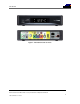
Introduction Figure 1 – IPC1100 Front and rear views IPC1100 Advanced IP Client Video Set-top • Installation and Operations Manual 2 365-095-24769 x.
Introduction Features Tuners • The IPC1100 uses MoCA to communicate to the VMS1100 Gateway. Audio and video content, as well as entitlement messaging, are delivered over MoCA.
Introduction Table 1 – (VMS) DVR Recording Time Guidelines Estimated Recording Hours For: Internal drive size Standard Digital Channels HDTV Channels 1 TB 350 to 444 90 to 150 All times are approximate. The actual hours a subscriber can record are a function of program bit rate, the IPG type, and the reserved buffer space. Standard Data Features • 512 MB flash memory • 1024 MB SDRAM • One rear Universal Serial Bus (USB) 2.
Introduction Getting Help Help with your ARRIS product is available online and by phone. Help with your product is available online and by phone. Find technical documentation in the CustomerCare 360 Documentation Center (http://www.arrisi.com/cc360). Get release updates and download software from DigitalCM (digitalcm.arrisi.com). The ARRIS Training Learning Portal provides self-paced product training and course descriptions of instructor-led training classes at http://www.arris.com/support/training.
Overview Overview 2 Front Panel The front panel controls provide on/off functionality only. Most functions, such as those requiring a numeric entry, require a remote control. The Power button blinks when receiving a signal from the remote control. Figure 2 – IPC1100 front panel Table 2 – Front panel Label Description 1 Power 2 Display panel IPC1100 Advanced IP Client Video Set-top • Installation and Operations Manual 6 365-095-24769 x.
Overview Rear Panel The rear panel contains connectors for video, audio, and RF cabling, data output, and data interface connectors. Some connectors are not enabled and require the support of application software.
Overview System Overview This section introduces key concepts relevant to installing the ARRIS Whole Home IP Video Network CPE. It describes: • • • • The passive optical network (PON) connecting the customer premises to the headend The ARRIS Whole Home IP Video Network that you install at the customer premises Multimedia Over Coax Alliance (MoCA) technology Multi-room DVR The ARRIS Whole Home IP Video Network connects to the fiber-to-the-premises (FTTP) passive optical network (PON).
Overview The FTTP PON carries the following services: Service Description Two-way video service (to VMS only) Video services include enhanced interactive services such as video on demand (VoD). Video is carried over the PON to the ONT and then over the in-home coaxial network. Digital and out-of-band (OOB) carriers are supported on the 50 to 862 MHz spectrum.
Overview Figure 5 – Whole Home IP Video CPE overview The components include: • • • ARRIS or similar optical network Broadband Home Router (BHR) with embedded MoCA ARRIS VMS/IPC advanced /IP set-tops containing embedded MoCA technology: ο VMS1100 hybrid QAM/IP digital gateway/DVR ο IPC1100 advanced digital set-top supporting HDTV You must connect the BHR to an RF coaxial splitter connecting to the coaxial cable wall outlets in the other rooms in the customer’s premises.
Overview MoCA MoCA technology bridges Ethernet traffic onto the coaxial cable network. MoCA 2.0 operates from 975 to 1025 MHz on the MoCA WAN channel when a MoCA 1.1 BHR is present and 1125 to 1175 MHz on the MoCA LAN when communicating with MoCA 1.x devices; and 1125 to 1225 MHz on the MoCA LAN when communicating with any MoCA 2.0 devices. MoCA 2.0 operates from 1350 to 1675 MHz on the MoCA WAN channel when a MoCA 2.0 BHR is present.
Overview Link-Local IP addressing enables MoCA set-tops to operate on a private local area network (LAN) using a defined range of reserved IP addresses. The MoCA set-tops in a home automatically self-assign an IP address in the range above 169.254.1.18. The Link-Local address space is registered with the Internet Assigned Numbers Authority (IANA). For detailed information about Link-Local addressing, visit www.faqs.org/rfcs/rfc3927.html.
Installation Installation 3 Whole Home IP Video Network Installation This section provides instructions to connect the ARRIS Whole Home IP Video Network. Figure 9 – MoCA Set-Tops Note: Always be sure to follow all of the Important Safety Considerations. Before You Begin Before you move or change components on the subscriber’s entertainment system: • • • Be sure you have all required tools and equipment. • Check the home entertainment system.
Installation Be sure you install the media hub before connecting any other set-tops. • From the labels on the bottom of each device, record the STB MAC address and serial number of each set-top. Figure 10 – IPC1100 Set-Top MAC Addresses During the installation: 1. Connect the home router. 2. Connect the VMS via the home coaxial network. 3. Connect the IP Client via the home coaxial network. 4. Connect the A/V connections for each set-top to the home theater equipment.
Installation Table 4 – Sample table listing signal levels and MAC Addresses Cable Outlet Set-top Serial Room Signal Level MAC Address Set-top Type Router -2 dBmV 001225xxxxxx None Living room -6 dBmV 001225xxxxxx VMS1100 Den -8 dBmV 001225xxxxxx IPC1100 Master bedroom -16 dBmV 001225xxxxxx IPC1100 Number 5. Use your TV signal tester at the coaxial outlet where you will connect any MoCA set-top box and router.
Installation Table 5 – IPC1100 video outputs Connection Type TV Type Description Component (YPbPr) HDTV and SDTV The YPbPr outputs provide component video, the most widely supported HD video connection. HDMI HDTV and SDTV • HDMI offers higher quality HD video than component video. • HDMI providess both video and audio connections. If you use HDMI, no separate audio connection to the TV is required. • HDMI is compatible with DVI.
Installation Installation Overview 1. Determine if you are connecting to a: Device Connection High-Definition TV or monitor Use the component video (YPbPr) or the HDMI output. No other video connection supports HDTV. If the TV has no HDMI input but does have a DVI input, connect a DVI-to-HDMI adapter or cable to the HDMI out connector on the IPC1100 set-top, and the DVI-HDTV connector on your TV. Note: A separate audio connection will be needed.
Installation Cabling to an HDTV for Video For the best possible HDTV video quality: 1. If the TV has an HDMI input, connect it to the IPC1100 HDMI output. If the TV has a DVI input, you can connect it to the IPC1100 HDMI output using an HDMI-to-DVI converter cable or adapter. ο L/R audio connection or digital audio S/PDIF connection is required for sound with a DVI connection. 10. Otherwise, use the component video (Y, Pb, and Pr) connectors.
Installation Cabling to an HDTV for Audio Figure 12 – Cabling to an HDTV for Audio IPC1100 Advanced IP Client Video Set-top • Installation and Operations Manual 19 365-095-24769 x.
Installation Cabling to a High-Definition TV and an A/V Receiver for Video Figure 13 – Cabling to an HDTV and A/V Receiver for Video Note: If the A/V receiver includes an HDMI input & output, the IPC1100 HDMI output can be connected directly to the A/V receiver. Because HDMI provides both video and audio output, no additional audio connections to the A/V Receiver and TV are required. IPC1100 Advanced IP Client Video Set-top • Installation and Operations Manual 20 365-095-24769 x.
Installation Cabling to a High-Definition TV and an A/V Receiver for Audio Figure 14 – Cabling to an HDTV and A/V Receiver Note: If the A/V receiver includes an HDMI input & output, the IPC1100 HDMI output can be connected directly to the A/V receiver. Because HDMI provides both video and audio output, no additional audio connections to the A/V Receiver and TV are required. IPC1100 Advanced IP Client Video Set-top • Installation and Operations Manual 21 365-095-24769 x.
Installation Cabling to a Standard-Definition TV Figure 15 – Cabling to a Standard Definition stereo TV IPC1100 Advanced IP Client Video Set-top • Installation and Operations Manual 22 365-095-24769 x.
Installation Data Device Connections The IPC1100 rear panel provides the following data ports: Port type Description USB 2.0 Optional for future use Ethernet 10/100 Mbps RJ-45 port IPC1100 Advanced IP Client Video Set-top • Installation and Operations Manual 23 365-095-24769 x.
Installation Autoprovisioning Users will be guided through a series of steps, and self-checks to ensure proper installation and system readiness. The IPC1100 will run through a series of self tests and registration routines before becoming ready. The guide will be in a “wizard” mode in which the health and status is displayed and an instructional procedure will be presented to assist you to properly rectify any problems in the process.
Installation Figure 16 – Welcome-Start Activation Screen. Figure 17 – Overlay screen during AP in an error state. Press A to switch to detail screens. IPC1100 Advanced IP Client Video Set-top • Installation and Operations Manual 25 365-095-24769 x.
Installation Figure 18 – Health checks begun. Figure 19 – Example error screen. IPC1100 Advanced IP Client Video Set-top • Installation and Operations Manual 26 365-095-24769 x.
Installation Figure 20 – Step 2 Software Download Figure 21 – Step 3-Activation Screen IPC1100 Advanced IP Client Video Set-top • Installation and Operations Manual 27 365-095-24769 x.
Installation Figure 22 – Activation Complete Screen Registration with the Media Server Before the IPC can be used to provide service it has to register with the Verizon Media Server (VMS). The information needed for the registration to occur successfully will typically be known to the management server prior to the installation of the unit. The installer might offer additional IPC units to the subscriber at the time of installation.
Installation Operational Check for the Remote Control The operational check tests communication with the remote control: Feature Testing Procedure Power on Press power on the remote control to turn on the IPC1100. Tune the television to the output channel (3 or 4) if using the RF output. Channel selection Scan through the channels using the channel + or - keys. Tune to several channels by entering the channel number using the numeric keys.
Installation Figure 23 – Basic User Interface Main Menu Optimizing the High-Definition Settings This subsection describes how to optimize SD and HD video settings and closed captioning based on subscriber preferences. Before you optimize the output settings: 1. Connect the IPC1100 set-top to other home entertainment devices. 2. Plug the IPC1100 set-top into a power outlet. 3. Ensure that the IPC1100 has completed the auto provisioning process and has connectivity to a VMS through the home network. 4.
Installation Figure 24 – User Settings. Use the remote control or the cursor keys on the front panel to navigate the on-screen menus: • • • • Press the ▲ and ▼ keys to highlight the setting you wish to change. Press the ► or OK key to select an option. To exit the setting and move to another setting, press the ▲ or ▼ key. To exit the menu and save your settings, press the power or menu key.
Installation The User Settings menu options are: Setting Description TV Type Allows you to specify the style of television connected to the IPC1100 set-top. Options include 16:9, 4:3 LETTERBOX, and 4:3 PAN SCAN. By default, the 16:9 option is selected. The options are used as follows: • 16:9 designates that a widescreen television is connected to the IPC1100 set-top.
Installation Additional HDMI Settings The Additional HDMI Settings menu is used to configure advanced options that affect the operation of the IPC1100 with HDMI and DVI display devices. Adjustable options include display mode, color space, audio output mode, audio lip sync delay, and 1080p passthrough. The Additional HDMI Settings menu screen is illustrated and defined below.
Installation YCC 4:4:4 — The IPC1100 will generate video signals within the YCC color space. RGB — The IPC1100 will generate video signals within the RGB color space. Note: Adjusting these settings could result in a loss of video. Only a professional installer or someone with a good working knowledge of the color spaces supported by the TV should change this setting. Audio Output The Audio Output setting allows you to specify the digital audio format delivered over the HDMI output by the IPC1100.
Installation Additional Closed Caption Settings Menu The Additional Closed Caption Settings menu is used to adjust the various display options for closed caption legibility. Customizable options include font size, font style, font color, and font opacity. You may also select to view different closed caption services if these are included within the broadcast program. The Additional Closed Caption Settings menu screen is illustrated and defined below.
Installation Setting Description BLUE, YELLOW, MAGENTA, or CYAN. Font Opacity Sets the opacity. Defaults to AUTO. Options are AUTO, TRANSPARENT, TRANSLUCENT, SOLID, or FLASHING. Font Edge Type Sets the edge appearance — AUTO, NONE, RAISED, DEPRESSED, UNIFORM, LEFT SHADOWED, or RIGHT SHADOWED. The default is AUTO. Font Edge Color Sets the edge color — AUTO, WHITE, BLACK, RED, GREEN, BLUE, YELLOW, MAGENTA, or CYAN. The default is AUTO. Backgroun d Color Sets the background color for closed captions.
Diagnostics Diagnostics 4 Diagnostics are displayed on the on-screen display (OSD) and front-panel display.
Diagnostics Figure 25 – Example of the front panel display for the main menu You can use the following keys to navigate the diagnostics menus: 3. Press channel ▲, channel ▼, cursor ▲, or cursor ▼ to select 01 through 17. 4. Press cursor ◄, cursor ►, select or enter to execute the selected diagnostic. 5. Select Exit from the Remote or press Power to exit. IPC1100 Advanced IP Client Video Set-top • Installation and Operations Manual 38 365-095-24769 x.
Diagnostics 01 General Status This diagnostic displays general system status information on the OSD and front panel. The information is updated each time the diagnostic is displayed. Note: Grayed out menu items do not pertain to the IP Client and therefore are not selectable from the Main Diagnostics menu. IPC1100 Advanced IP Client Video Set-top • Installation and Operations Manual 39 365-095-24769 x.
Diagnostics Environment Error Figure 26 – Example General Status display (no error) The General Status fields are: Field Description Error Error codes display on the front panel and OSD when an error occurs.
Diagnostics Field Description EP09 Battery test failure EP11 Invalid unit address EP12 Power on self test failure EP14 GITV startup failure EP15 TSI structure corrupt EP18 Driver initialization failure Platform ID A unique, 16-bit hexadecimal number that identifies the platform (also called the ROM ID). Chip Set Identifies the Chip Set used by the hardware. Family ID The manufacturer and product family, in hexadecimal. Model ID The model, in hexadecimal.
Diagnostics 02 Unit Address/Security This diagnostic displays the unit addresses. Field Description Host Serial No. The Host Serial Number is displayed on the Unit Address diagnostic screen. MAC Addresses Installed The MAC addresses are stored in protected flash and displayed in hexadecimal. The front panel will display the unit address of the device when the Address/Security screen is displayed, if the device supports a unit address.
Diagnostics 03 Code Module IPC1100 Advanced IP Client Video Set-top • Installation and Operations Manual 43 365-095-24769 x.
Diagnostics If a download is in progress, the completion percentage for the current download will display on the IPC1100 front display panel. Figure 27 Example Front Panel Display for Code Download status The Code Modules fields are Field Description Group ID Identifies the product configured Group. Region ID Identifies the product configured Region. Primary Server Download Path Primary method for Code download.
Diagnostics Field Description Secondary Server Download Path Secondary method for Code download. Options are: "Multicast" "Unicast" "N/A ‘Undefined”" Code Installation May Start Time Configured time from the MRL when the product may start to download. Code Installation Must Start Time Time from the MRL when the product must start to download. Code Installation Start Time Date and time (local time) when the code installation was started.
Diagnostics Field Description Last Successful MRL IPMC Join Time The time when the product last successfully joined the MRL multicast, if available. MRL Error The error, if any, occurred during download, expressed in the format "DLxx".
Diagnostics Field Description Number of Bytes Downloaded An Indicator of download progress provides the current value of the number of bytes received Download Start Time The date and time (local time) when the object download started. Download Complete Time The date and time (local time) when the object download completed CDL % Complete An Indicator of download progress provides the current percent complete of the object download.
Diagnostics 05 HTTP Adaptive Video Information For Over the Top Video Services. Field Description Buffer Fullness Indicates the percent fullness of the buffer in the receiver. Buffer Status The status of the receiver buffer indicating if overrun or underrun is detected. Values are: "Overflow" "Underflow" "OK" Stream Type The type of the stream received over the top. Examples are: "HLS" "Progressive DL" Acquisition Time Time taken to acquire the last segment, expressed in milliseconds.
Diagnostics Field Description Sequence Number The sequence number of the segment which is currently being played. Segment Duration Duration of each chunk or segment expressed in milliseconds. DRM Type The type of DRM being used. Possible values are: "SecureMedia" "Vz AES-128" "N/A" Source IP IP address of streamer server Source Port The port of streamer server that is being used for the OTT streaming.
Diagnostics 06 In Home Streaming Field Description Local IP Address IP address of the local device receiving the stream. Source IP IP address of the streamer server for an incoming stream. Source Port The port of the streamer server that is being used for the current streaming session (incoming to the current STB). Fail to Establish Secure Stream This parameter indicates when a client device fails to set up a secure stream with a server. The client STB will set it to TRUE in case of failure.
Diagnostics 07 Audio / Video Status The Audio/Video Status fields are: Field Description SPDIF Indicates S/PDIF Mode as set by application software. N/A Audio S/PDIF mode is not applicable. IEC958PCM PCM audio selected. (Dolby Digital) For Dolby Digital selection, the following speaker selection is set: 1/0 right front or left front. 2/0 right front and left front. 3/0 right front and left front and center. 2/1 right front and left front and (right rear or left rear).
Diagnostics Field Description Audio Mode Audio Mode indicates the audio Mode of in incoming digital service. Valid values include: • N/A: the audio mode is not applicable to the currently tuned stream. • Mono: the audio mode is monophonic. • Stereo: the audio mode is stereo. • Surround: the audio mode is surround sound. • 5.1: the audio mode is Dolby Digital 5.1 surround sound. • 7.1: the audio mode is Dolby Digital 7.1.
Diagnostics 08 Memory Configuration The Memory Configuration fields are: Field Description Total Memory The allocated system RAM in MB. Memory Free The size of free RAM memory expressed in Megabytes (MB). Total CPU Load The total process load on the CPU. CPU Load Average CPU load percentage per process. % CPU and Memory Per Process RAM Memory Used Per Process (scroll down for more processes). IPC1100 Advanced IP Client Video Set-top • Installation and Operations Manual 53 365-095-24769 x.
Diagnostics 09 Interface / Port Status IPC1100 Advanced IP Client Video Set-top • Installation and Operations Manual 54 365-095-24769 x.
Diagnostics The User Setting fields are: Setting Description DVI/HDMI Port If a device is connected to the HDMI port only, the following diagnostics display to help troubleshoot the HDMI interface. They all display “N/A” if no device is connected to the HDMI port or the value is invalid or cannot be retrieved.
Diagnostics Setting Description CC Analog Service Selection Analog: CC1, CC2, CC3, CC4, T1, T2, T3, or T4. The default is CC1. CC Digital Service Selection Digital: PRIMARY LANGUAGE, SECONDARY LANGUAGE, 3, 4, 5, or 6. The default is PRIMARY LANGUAGE. Detection of 3DTV Primary Formats Indicates if 3D video timing formats are read from the Extended Display Identification Data (EDID) register for the connected device.
Diagnostics 10 Current Sessions Field Description OTT Stream Number of Over The Top (OTT) HLS streams detected (0 or 1 session) OTT (Over-The-Top): Should a host VMS go offline, an OTT session will be started for clients connected to said VMS that will allow connected clients to continue TV viewing. NOTE: An OTT session has a limited/scaled back channel map so not all channels will be available for the IP clients.
Diagnostics 11 Connected Home Field Description Network Link Type The type of the link. Possible values are "MoCA" "Ethernet" "None" The value is set to "None" to indicate that a connection is not established yet. LAN MAC Address MAC Address assigned to the Local Area Network Moca Link Status The status of the MoCA link. TRUE = Active FALSE = Inactive MoCA Connectivity Loss Count Number of times MoCA connectivity was lost since last boot. Ethernet Link Status The status of the Ethernet link.
Diagnostics Field Description RF Freq Displays the frequency of the MoCA RF channel in use by the set-top, in MHz, from 1150 to 1500 MHz. The default is 1150 MHz. RF Password RF MoCA Password used to establish the home network. Number Of Nodes In Network The total number of nodes (i.e. devices) residing on the MoCA network. Number Of Nodes Connected to the Local Device The total number of MoCA nodes/devices connected to the node/device which is being queried.
Diagnostics 1. Field 2. Description Tx Rate The physical layer transmit rate of the STB being polled to the connected node (indicated by nodeID), expressed in Mbps. Rx Rate The physical layer receive rate by the STB being polled from the connected node (indicated by nodeID), expressed in Mbps. Phy Rate Table Note: These indicators can appear next to the node ID (to the left) should the condition occur.
Diagnostics Field Description Tx Attenuation Level MoCA transmit attenuation level (dB) for each direct link between the local device and each MoCA node on the MoCA network, if available. MoCA Tx Power The RF transmit power level at the connected MoCA node expressed in dBmV for the link between the connected node and the STB being polled. MoCA Rx Power The RF receive power level at the STB being polled expressed in dBmV for the link between the connected node and the STB being polled.
Diagnostics Field Rx Packet Count Description MoCA received packet count for each direct link between the local device and each MoCA node on the MoCA network, if available. Uncorrectable PER This parameter indicates the fraction of received packets that could not be corrected for the time period within PERWindow. The value is expressed in 10-7. E.g. the value 5 will represent the PER 5E-7. PER Window Window time in minutes for PER calculation. Expected range would be 60 minutes to 240 minutes.
Diagnostics Field Description Traffic Type Traffic type that is to be tagged. Priority LAN The priority code point setting of a particular traffic type as defined by IEEE 802.1p. The possible values are 0-7. N/A is used to indicate that Priority is Not Assigned. DSCP Mark DSCP value to be used. IPC1100 Advanced IP Client Video Set-top • Installation and Operations Manual 63 365-095-24769 x.
Diagnostics Field Description Ethernet MAC Address MAC Address assigned to the Ethernet. Driver Loaded This parameter indicates whether Ethernet Driver is loaded. TRUE = Loaded FALSE = Not loaded Flow Control This parameter indicates whether flow control has been enabled. TRUE = Enabled FALSE = Disabled Jumbo Packet This parameter indicates whether Jumbo packets have been enabled. TRUE = Enabled FALSE = Disabled Link Speed The link speed expressed in Mbps. The values are 10, 100 and 1000.
Diagnostics Field Description Discovered VMS List List of IP addresses of the VMS’s discovered in the home network. Additional pages will be displayed as needed to display VMS’s. IPC1100 Advanced IP Client Video Set-top • Installation and Operations Manual 65 365-095-24769 x.
Diagnostics Field Description IP Address IP Address of the device's DHCP Server (BHR). Subnet Mask Subnet Mask of the DHCP Server. IP Address Lease Time Date and time (local time) when the IP address was assigned by the BHR Time Remaining Time left for the IP lease to expire. This is expressed in seconds. IP Address Renewal Attempt Count The number of times the IP Address was attempted for renewal since last reboot.
Diagnostics Field Description Wake On LAN Indicates whether the WOL feature is enabled. TRUE = Enabled FALSE = disabled Status VLAN/QoS This parameter indicates whether VLAN 802.1p status is enabled. TRUE = Enabled FALSE = Disabled Traffic Type Traffic type that is to be tagged. Priority LAN The priority code point setting of a particular traffic type as defined by IEEE 802.1p. The possible values are 0-7. N/A is used to indicate that Priority is Not Assigned. DSCP Mark DSCP value to be used.
Diagnostics 16 WAN Status Field Failed Inform Count Description The number of failed Inform attempts since the last successful Inform. IPC1100 Advanced IP Client Video Set-top • Installation and Operations Manual 68 365-095-24769 x.
Diagnostics 17 Keypad Status The front panel key presses should also highlight the corresponding character and a front panel indication. Also, a segment on the front panel 7-segment display should illuminate with each press of a front panel key. This diagnostic verifies the functionality of the front panel indicators and the front-panel keypad. Each highlighted character corresponds with a front-panel key press.
Diagnostics Troubleshooting 5 Troubleshooting guidelines follow. If problems still occur after performing the diagnostics, call the TAC for assistance as described in the Introduction. Table 6 – Troubleshooting Guidelines Problem Possible Solution The IPC1100 settop will not power on The IPC1100 set-top may have received a software update and may not power on while the new software is being installed. Try again in a few minutes.
Diagnostics Problem Possible Solution There is no audio from the center and/or surround speakers of a home theater receiver connected to the IPC1100 set-top Not all Dolby® Digital programs feature full 5.1 surround sound. In some cases, the programs may only contain left and right stereo audio. • Verify that the S/PDIF cable (coaxial or optical) is firmly connected to the IPC1100 set-top and the home theater receiver.
Diagnostics Problem Possible Solution There are black bars above and below the picture All 4:3 HDTVs display HD programs in letterbox format (black bars above and below the picture) because of the shape of the display screen. • Set the TV TYPE to 4:3 Pan-Scan. This enables the IPC1100 to remove the black bars above and below the picture when possible. Some SD programs are broadcast in the letterbox format with black bars above and below the picture.
Diagnostics IP Network Issues Insufficient RF Network Throughput If the RF light on the BHR is flashing after you connect it to a set-top, use the Connected Home Status diagnostic to display the data rate for each MoCA network link (see Troubleshooting) The Transmit data rate between each MoCA node is shown on the Link Status page. The MoCA node can be correlated to the MAC address of each device on the Connected Home diagnostic.
Diagnostics Bypassing an Amplifier To bypass the MoCA signal around an in-line amplifier that cannot handle two-way traffic nor has insufficient bandwidth for MoCA: 1. Locate the line amplifier by tracing the coaxial cable back towards the ONT. 2. Disconnect the existing RF cable from the amplifier. 3. Move the existing amplifier to a position near the point of entry. As shown in the figure below, connect each existing coaxial cable to the diplexer.
ARRIS Enterprises, Inc. 3871 Lakefield Drive Suwanee, GA 30024 www.arrisi.com 365-095-24769 x.