
User's Manual


2
2 Product profile
2.1 Description
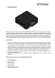
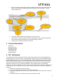
Figure 1: Radar proximity sensor block diagram
As depicted in figure above, the sensor comprises two printed circuit board assemblies (PCBA)
namely RF Board and Host Board which are connected internally through a board-to-board
connector. The sensor interfaces with rest of the system through an external connector which
brings power and system communication bus to the sensor. The sensor can operate from a
wide input voltage range, 12 – 36 VDC, and communicates with rest of the system over twisted
pair cable using Controller Area Network Flexible Data-Rate (CAN-FD) data-communication
protocol.
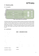
2.2 Specification
Electrical
Operating voltage
Power rating
12.5W
Communication Interface
Physical layer
Twisted pair differential signal
Protocol
Controller Area Network Flexible Data-Rate (CAN-FD)
Data rate
upto 5mbps
Object detection - Azimuth
Type
Static and Dynamic
Range measurement
0.05 - 225 m
Velocity measurement
0 - 92 kmph
Azimuth beamwidth
+/- 60° (depending upon antenna array implementation)
Elevation beamwidth
+/- 30° (depending upon antenna array implementation)
minimum object to object
separation in range
0.039m
minimum object to object
separation in velocity
0.32m/s
Environmental
10VDC ~ 14VDC(Nominal 12VDC)
22VDC ~ 26VDC(Nominal 24VDC)