
User's Manual


4
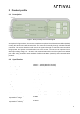
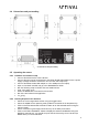
2.4 Dimensions and part marking
Figure 3: Dimensions and part marking
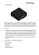
2.5 Operating the sensor
2.5.1 Hardware and software setup
• Connect the RPSS device to the CAN bus
• Connect the other end of the CAN bus to the PEAK PCAN USB adapter and to a power
supply (Voltage should be set between 12V and 20V and 2Amp max).
• Connect the PEAK PCAN USB adapter to a free USB port on the laptop.
• Open a Linux Bash terminal and go to the $HOME/Arrival folder
• Run the following script to initialize the Host CAN interface
• sudo ./can_bring_up.sh
• Power the RPSS device and wait for 20 seconds.
• Run the CAN Transmit GUI application
• ./tx_gui.py
2.5.2 Running Graphical User Interface
• Select A1 for the target RPSS sensor using the toggle button.
• Select the USRR sensor operating mode (USRR is the default in the dropdown list).
• Click on the “Execute transmit command” button to run the selected sensor using the
selected mode.
• Sensor activation log messages should show up in the white panel status.
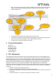
• Click on the “Start visualization” button to display the sensors visualization using the
ROS/Rviz external tool. You should see point clouds detected by the red 3D box (A1
RPSS device) on the visualization.