380037
Contents Page Page WARNINGS 3 FACTORY CHASSIS SETTINGS 17 KIT OVERIVIEW 3 CHASSIS TUNING 19 REQUIRED 4 Ride Height 19 BATTERY CHARGING 4 Camber Link Length 19 5 Steering Arm Length (Toe In/Out) 19 CHASSIS OVERVIEW Safety Instructions for Batteries 5 Camber Link Position 19 RADIOGEAR 6 Shock Position 19 Overview 6 Shock Removal 20 Steering Trim 6 Springs 20 Throttle Trim 6 Shock Oil 20 Binding 6 Dual Rate 7 Gear Chart 21 Battery Status 7 Spur/Pinion Gear Rem
Battery Mode Batteriemodus Mode de Batterie Modo de batería ክአኣዙዙኦ 䟄㻯㲰㆞ If using LiPo batteries you must set the correct battery mode on the ESC (electronic speed controller) to prevent battery damage. Wenn Sie LiPo-Akkus verwenden, muss der entsprechende Batteriemodus am Fahrtregler angewählt sein, um Schäden an der Batterie durch Tiefentladung zu verhindern.
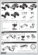
Kit Overview ARRMA ADX-10 ARRMA Fury ARRMA Granite ARRMA Mojave 1.3mm 1.5mm 2.0mm 2.5mm Hex Wrenches Shock pre-load spacers ARRMA Raider ARRMA Vorteks Cross wrench US Design Patent application no. 29/392 417 Community Design No: 001275770-0001 Receiver Bind Plug Kit # 102530 > 102537 _ATY/CTY/GTY/ITY Kit # 102530 > 102537 _TY Kit # 102530 > 102537 _ATN/CTN/GTN/ITN A R R M A AT X 2 . 4 . G h z Transmitter 7.
Safety Instructions for Batteries 1. Use only four(4) AA alkaline batteries in your ATX100 transmitter. 2. Do not dispose of the battery in a fire as it may explode. Check with local codes for possible special disposal instructions. 3. Do not open or mutilate the battery. Released electrolyte is corrosive and may cause damage to the eyes and skin. It may be toxic if swallowed. 4.
Radio Gear ARRMA ATX100 2.4Ghz Aerial Control Panel Steering reverse Throttle reverse Power LED Battery Status LED Control panel Steer wheel (CH1) Steering trim Throttle trim Bind button Steering dual rate Power switch Throttle trigger (CH2) Status LED BAT socket (not used) Bind/CH3 socket Throttle socket (CH2) Battery compartment Steering (CH1) socket Aerial Steering Trim Throttle Trim Throttle Trim: factory default zero, adjustment is not necessary.
Dual Rate Battery Status If battery status LED is flashing, the batteries need to be replaced. Contains FCC ID: ZL4-KST-HXGT2 Factory Defaults Steering/throttle channels switches set to ‘N’, Steering and Throttle trim set to middle/zero adjustment. Steering Dual Rate at 100%/fully right. This device complies with Part 15 of the FCC Rules.
Throttle Setup Do not move the throttle when switching the model on and the ESC will automatically set the throttle neutral. A long beep will sound to confirm setup. ESC Status LED Temperature Protection If the ESC temperature exceeds 80 degrees Celsius for 5 seconds or longer, the ESC will enter temperature protection mode and the status LED will blink quickly. Once the ESC has cooled down it will resume normal operation.
Battery Fitting AA x4 ii i Running i i ii ii Driving Fundamentals We design all ARRMA cars to be fun and quick to get used to. However, it is important to be comfortable with the handling before exploring the upper reaches of your car's performance. For the first run we recommend taking your kit to an open, flat area (such as a park) ensuring you are away from potential hazards, people or animals. Start by simply driving round in a large loop, slowly building up speed to get used to the handling.
Maintenance Recommended Tools Supplied Allen Keys Not Supplied Hex Drivers Nut Drivers 1.3mm (0.050") 5.5mm 1.5mm 7mm 1.3 (0.050"), 1.5, 2, 2.5mm Turnbuckle Wrench 2mm 4mm Cross wrench 2.5mm Grease Thread-lock HAZARDOUS/FLAMMABLE: Adult supervision required, use only in a well ventilated area and away from sources of ignition.
Trouble Shooting Matrix (cont.) Problem Possible Cause Solution Neutral throttle position of electronic Set throttle trim to zero and switch electronic speed control (ESC) incorrect. speed control (ESC) off and then on again, a chime to indicate the new neutral position has been set SLUGGISH PERFORMANCE Slipper clutch adjustment too loose Check slipper is set to factory setting or your (continued) prefered setting. Electric motor dirty or damaged Clean, check condition and/or replace - visit ARRMA-RC.
Chassis Maintenance Online videos when you see this icon >> Tools Required Cloth ARRMA-RC.COM/ SUPPORT/ Automotive Brake Cleaner or Nitro Car Cleaner Brush AFTER RUNNING: Ensure that drivetrain, suspension and steering are clean, free and lubricated Check that all the screws are tight Check tyre/wheel condition DO NOT RUN THE CAR IF ANY PARTS ARE DAMAGED Please contact your local distributor to order replacement parts. N.B.
Slipper Clutch Adjustment ARRMA-RC.COM/ SUPPORT/ Tools Required The function of the slipper clutch is to protect the gearbox, differential and motor from shocks and also to allow you to tune how the torque from the motor 'comes-in' when you accelerate to suit different surface conditions. To adjust the slipper clutch do the following: 2mm Hex Driver 5.
Slipper Pad Replacement ARRMA-RC.COM/ SUPPORT/ Tools Required Every 20 runs or so it may be necessary to replace your slipper clutch 'pads'. This depends on how the slipper is setup and your driving style. If you find that it is hard to get the setting you want from your slipper clutch then it is likely that the pads need to be replaced. 2mm Hex Driver 5.
Driveshaft Maintenance ARRMA-RC.COM/ SUPPORT/ Every 20 runs or so it may be necessary to clean and re-grease the drive-shafts as well as check for wear and/or damage. Running in dusty, sandy or wet conditions will mean that this will need to be performed more frequently. Tools Required Cloth 7mm Nut Driver or Cross Wrench Grease Long-nose Pliers 2 1 Remove rear wheel with 7mm nut-driver/cross wrench. Separate camber-link from balljoint with pliers. Remove driveshaft.
Rear Axle Maintenance (cont.) 3 4 Rotate rear hub carrier to allow better access and push axle up through bearings. 5 Clean and check condition of rear axle. If worn as shown above, replace axle. Refit driveshaft, camber-link, drive pin, rear hex hub and rear wheel. Wheel Bearing Replacement ARRMA-RC.COM/ SUPPORT/ Ev er y 50 r uns or so it may be necessary to inspect the wheel bearings for wear.
Factory Settings Front Shocks 26mm 1.5mm Front Ride Height 27.5 mm -1.0 2 x 1.3mm ° 350 cst 350 cst ° Spring 45mm 63.5gf/mm 70mm 40gf/mm Toe Angle 0 (Zero) 2 x 1.3mm Oil wt. Camber Lower shock position Rear Piston Rear Differential Camber Link position 28 mm Camber -0 24.5mm 3000 cst Oil wt. Ride Height ° Motor/Gears Motor Spur Gear MEGA 15T 81T 48dp ESC Pinion Gear MEGA 22t 48dp Lower shock position Factory Settings Front Shocks 26mm Front 1.5mm 27.5 mm -1.
Factory Settings Front Shocks 41.5mm Front 0.75mm 38.5 mm 0 (Zero) 2 x 1.3mm ° 350 cst 350 cst ° Spring 50mm 73.5gf/mm 72mm 47gf/mm Toe Angle Lower shock position 2 x 1.3mm Oil wt. Camber -1.0 Rear Piston Ride Height Rear Differential Camber Link position 39 mm Camber -0 46.5mm 3000 cst Oil wt. Ride Height ° Lower shock position Motor/Gears Motor Spur Gear MEGA 15T 87t 48dp ESC Pinion Gear MEGA 18t 48dp Factory Settings Front Shocks 41.5mm Front 0.75mm 38.
Chassis Tuning N . B . Ra i d e r s h o w n a s a n exa m p l e - i n f o r m a t i o n a p p l i e s t o a l l v a r i a n t s . Ride Height 1mm 3mm 7mm The ride height is set using preload spacers between the top of the shock and the top of the suspension springs. These plastic clips are included in the kit in 1mm, 3mm and 7mm versions. Raising the ride height not only gives you greater ground clearance when running on more uneven surfaces but it can also affect the chassis balance of the car.
Shock Removal ARRMA-RC.COM/ Tools Required SUPPORT/ Ever y 50 runs or so it may be necessary to change the shock oil because over time it will become thinner meaning kit handling could be affected. You can also use this as an opportunity to upgrade the springs or shock oil. 2mm Hex Driver Front 5.5 & 7mm Nut Driver or Cross Wrench Rear Remove lower shock bolt with 2mm hex driver. Remove upper shock nut with 5.5 nut driver or crosswrench. Remove shock absorber.
Drivetrain Tuning Gear Chart Your ARRMA kit has one gear ratio and this can be altered by changing the pinion or spur gear in the transmission. The standard gearing of your kit is designed to give the best compromise between speed and acceleration. Increasing the top speed will reduce acceleration and vice versa. Too low or high a gear will put strain on the motor/ESC, and potentially damage them. Pinion Gear (T=Tooth) 13T 14T 15T 16T 17T 18T 19T 20T 21T 22T 23T 24T 25T 26T 27T 28T 29T 30T 4.5 4.26 4.05 3.
Motor Removal ARRMA-RC.COM/ SUPPORT/ Tools Required Removing the motor is useful for cleaning the motor and also if choosing to upgrade to either a different specification brushed motor or the awesome power of an ARRMA GIGA brushless system! To see what motor upgrades are available for your car please visit ARRMA-RC.com or your local ARRMA distributor. 2mm Hex Driver 7mm Nut Driver or Cross Wrench 2 1 Remove rear right wheel with 7mm nut driver/cross wrench.
Differential Removal and Replacement ARRMA-RC.COM/ Tools Required SUPPORT/ 1.3mm Hex Driver 2mm Hex Driver 2.5mm Hex Driver 7mm Nut Driver or Cross Wrench Long-nose Pliers 2 1 Remove rear wheels with 7mm nut driver/cross wrench. Disconnect motor wires. Separate both rear camber-link ball joints with long-nose pliers. 4 3 Remove driveshafts on both sides. Use this opportunity to inspect axles and driveshafts for wear (Page 15). Remove long motor guard bolt with 2.5mm hex driver.
Differential Removal and Replacement (cont.) 8 7 Undo seven screws holding gearbox halves together. Notice that one screw is longer than the others. 9 Remove differential unit from gearbox. 11 10 Remove four screws holding differential together with 1.3mm (0.050”) hex driver. Remove top half of differential case, turn lower case upside down over a cloth and allow old silicone oil to drain. Refill differential with silicone oil to the level shown. Reinstallation is the reverse the removal process.
Radio-gear Maintenance Receiver Access ARRMA-RC.COM/ SUPPORT/ Tools Required If you want to replace or upgrade the steering servo, ESC (electronic speed controller) or re-bind the transmitter, you will need to access the receiver. 2mm Hex Driver 2 1 Remove four bolts securing receiver box lid with 2mm hex key, remove lid. Reinstallation is the reverse the removal process. (Raider only) Remove four roof bolts with 2mm hex driver, remove roof.
Steering Access (cont.) 6 5 4mm Inspect servo saver, ensuring that it is set to the factory setting above. Set with 7mm hex driver. Reassembly is the reverse the removal process. Disconnect servo arm ball-joint and remove steering assembly from servo box. Servo Removal Tools Required ARRMA-RC.COM/ 2mm Hex Driver SUPPORT/ Upgrading your servo will give quicker and more powerful steering.
© 2013 ARRMA Durango Ltd. A subsidiary of Hobbico, Inc.
DESIGNED FAST. DESIGNED TOUGH.
© 2013 ARRMA Durango Ltd. A subsidiary of Hobbico, Inc.
DESIGNED FAST. DESIGNED TOUGH.
© 2013 ARRMA Durango Ltd. A subsidiary of Hobbico, Inc.
DESIGNED FAST. DESIGNED TOUGH.
© 2013 ARRMA Durango Ltd. A subsidiary of Hobbico, Inc.
DESIGNED FAST. DESIGNED TOUGH.
© 2013 ARRMA Durango Ltd. A subsidiary of Hobbico, Inc.
DESIGNED FAST. DESIGNED TOUGH.
Option Parts and Upgrades AR220014 (Raider/ADX-10) AR310394 AR320186 AR340055 (23T) AR340057 (25T) Alloy Servo Arms Option Shocks Short Alloy Heatsink Motor Plate Alloy Wheelie Bar Axles AR220015 Option Shocks Long (Fury/Mojave/Granite/Vorteks) AR320157 Alloy Front Hingepin Brace AR320174 (SWB) Red Chassis TVPs AR320165 Wheelie Bar Set AR330148 (Front) Alloy Shock Tower Braces AR320162 (Rear) AR320175 (LWB) AR320176 Red Front Chassis Plate AR340056 (24T) © 2013 ARRMA Durango Ltd.
Settings Shocks Front Front Ride Height Rear Piston mm Oil wt. Camber Lower shock position ° Spring Toe Angle ° Rear Differential Camber Link position Oil wt. Ride Height mm Camber ° Motor/Gears Motor Spur Gear ESC Pinion Gear Lower shock position Settings Shocks Front Front Rear Piston Ride Height mm Oil wt. Camber ° Lower shock position Spring Toe Angle ° Rear Differential Camber Link position Oil wt.
Settings Shocks Front Front Rear Piston Ride Height mm Oil wt. Camber ° Spring Toe Angle ° Lower shock position Rear Differential Camber Link position Oil wt. Ride Height mm Camber ° Motor/Gears Motor Spur Gear ESC Pinion Gear Lower shock position Settings Shocks Front Front Rear Piston Ride Height mm Oil wt. Camber ° Spring Toe Angle ° Lower shock position Rear Differential Camber Link position Oil wt.