LCD DIGITAL PROPORTIONAL RADIO CONTROL SYSTEM Operating Manual
INDEX Transmitter Functions 03 Items Included 04 Specifications 04 Safety Warnings 04 Notice Before Using 05 Transmitter Controls 06 Menu Introduction 07 Other function of the transmitter 11 Receiver Information 12 How To Use The Transmitter 10 Binding your 2.4 GHz Radio System 13 Adjustments 15 Charging The Transmitter 14 Flow Chart 16 Statement: Specifications may change without notice, please refer to the real one for configuration. 2010.07 02 www.blitzrcworks.
Thank you for purchasing the ETC63- 2.4GHz Radio Control system. For safety precautions, you must read this manual before operating. BlitzRCWorks and the retailer are not responsible for any damage or loss resulted from improper usage and mishandling, as this will be the sole responsibility of the user. TRANSMITTER FUNCTIONS The ETC63- 2.4GHz is a newly developed 6 channel proportional transmitter and is the latest development of Art-Tech RC Hobby Corporation.
ITEMS INCLUDED 1. Transmitter: ETC63-2.4GHz 2. Receiver: ER62-2.4GHz 3.Manual The spare parts below is only offered in a complete set: 3 AS-100 9g Servos Simulator Cable Belt 9.6V Ni-MH Battery Charger CD Rom Specifications Number of channels: 6 Color: Black Charging Jack: Included Antenna Length: 15cm 3D Switch: Included Can be used on: Airplanes, and Helicopters Power Supply: 12V (1.
NOTICE BEFORE USING SIGNALS TO BE AWARE OF Please pay close attention to these signs below. They will appear in this manual as you read.
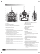
TRANSMITTER CONTROLS A B W C E F D G H I K M J L N P O S T U Q R V A:Antenna B:LCD(Liquid Crystal Display) ·Battery voltage of transmitter (battery energy level) ·Channels are on NOR or REV (Normal or Reversed) ·Estimated available flight time ·Menu setting ·Indicates state of lock or unlock ·Also displays: channel directions, data, option number, functions C:Throttle hold toggle switch D:Channel 5 toggle switch (should be in the up position) Channel 5 on aircraft can be used for mounted aerial
MENU INTRODUCTION After turning on the radio, the screen displays the time page. Press menu several times to enter into the main menu. Press the sub button at this time to enter into the sub menu. There will be a single beep sound to indicate a button pressed. If you do not hear any sound after pressing a button, check if the button is in place. It may be that the button you have pressed is not applicable in this menu so try pressing another button to hear for any sounds.
3.POPULAR OPTIONS Press the menu button to enter into Set menu. There are 5 sub menus that include D'R, Exp, Epa, Gyr, and Mrv. D'R (Dual Rate) settings: 1. Press the sub button 2. Press the left or right button to choose a channel (aileron, elevator, or rudder). 3. Press the Y/UP or N/DOWN button to increase or decrease the value input. The values set take effect when the D'R switch is switched on. The Dual Rate exponential curve may be set anywhere between 0% and 125%. Exponential settings: 1.
In C mode 1. Press the sub button to inter into the Swash menu (swash rate setting). Figure 1 shows 120º CCPM while Figure 2 shows 90º CCPM. 2. Press the Y/UP or N/DOWN button to connect the aileron to channel 1 or 6, elevator to channel 2, and pitch to channel 6 or channel 1 (not occupied by aileron). A is for aileron, E for elevator, and R for rudder. 3. Press the left or right button to choose an option. A is for aileron, E for elevator, and P for pitch. 4.
5.MIXING SETTINGS IN A, V, D MODE Press the menu button to enter into the Mix menu (mixing). There are 2 sets of mixing settings Mixing settings: 1. Press the sub button to enter into the Mix1 menu (mixing 1). 2. Press the left or right button to choose an option of using the master channel, slave channel or mixing proportion. 3. You can choose to use this option: Press Y/UP or N/DOWN button to confirm Yes or No (to cancel). Master channel option (Mas): press Y/UP or N/DOWN button to select it.
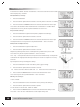
Mode 1 and Mode 2 settings: 1. Press the sub button to enter into the Mode 1 and Mode 2 settings menu. 2. Before setting the mode, make sure the plane is turned off (battery is unplugged). 3. Adjust the joysticks. The screws shown in the figure A and B help to suppress the springs. Screws C and D adjusts the resistance of the sticks. For Mode 1, loosen screws A and C but tighten screws B and D/ For Mode 2, loosen the screws for B and D but tighten A and C. 4. Press the left or right button to select a mode.
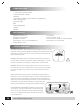
RECEIVER INFORMATION Specifications Indication that the receiver is working if it is tested between 4.8V to 6V Current drain rate: < 40mA Weight: 12g Dimension: 44mm x 23mm x 15mm Number of channels: 6 Range in height: > 350m Adjacent channel rejection: > -85dBm + 16kHz Function Connections for helicopters Connections for airplanes CH CH RECEIVER ER61-2.4GHz RECEIVER ER61-2.4GHz B. Battery/Bind B. Battery/Bind 6. Pitch 6. Pitch 5. Gyro gain 5. Landing Gear Retracts/ Bomb doors 4. Rudder 4.
HOW TO USE THE TRANSMITTER The correct power up process is to turn on the transmitter first with the throttle stick and throttle trim settings all lowered to its lowest position before turning on your aircraft.For operating helicopter ON A HELICOPTER If you are unfamiliar with how the helicopter can react to your commands on the transmitter or how to control your helicopter with the transmitter, you can see how it operates below.
ON AN AIRPLANE If you are unfamiliar with how the airplane can react to your commands on the transmitter or how to control your airplane with the transmitter, you can see how it operates below. Mode 1 Airplane Instructions: Ailerons: Move left joystick left for the left aileron to Elevator: Move left joystick up to have elevators go down and right aileron to go up.Move left joystick (horizontal tail) go up for the plane to rise up.
BINDING YOUR 2.4GHZ RADIO SYSTEM If this radio system is being used on a nitro gas powered aircraft, please connect the throttle into another channel first and then plug it into BATT channel on the receiver after binding. 1. Plug in the short-circuit plug (bind plug as shown with a small looped wire at the end) into the BATT channel on the receiver. Connect the ESC to the receiver for electricity to be sent to the motor. 2.
ADJUSTMENTS ADJUSTING CHANNEL VALUES 1. Enter into the Chv menu. 2. Press the left or right button to check whether the channels are in the right positions. Your settings for channels 1, 2, and 4 should be set to 0%. The minimum value of channel 3 should be -100% and the maximum should be 100%. If the curve setting value has changed, it should be set to the set value. If the values are different, please adjust the channels and its mid points.
Flow Chart (1-9,A,b,C) (1-9,A,b,C) (CH1-6) Key (CH1,2,4) Menu Sub Left right y/up n/down (CH1,2,4) (CH1-6) (A , E , r) (A,V,D) (A , E , P) (C) (PT1-5) (H, C) (PT1-5) (PT1-5) (PT1-5) (A,V,D) (Mix 2,3,4 Set as Mix 1 ) (CH1-6) (CH1,2,4,6) www.blitzrcworks.
www.blitzrcworks.