
Specifications

06
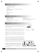
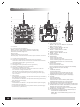
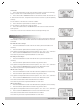
TRANSMITTER CONTROLS
A:Antenna
B:LCD(Liquid Crystal Display)
·Battery voltage of transmitter (battery energy level)
·Channels are on NOR or REV (Normal or Reversed)
·Estimated available flight time
·Menu setting
·Indicates state of lock or unlock
·Also displays: channel directions, data, option number, functions
C:Throttle hold toggle switch
D:Channel 5 toggle switch (should be in the up position)
Channel 5 on aircraft can be used for mounted aerial cameras,
retractable landing gear, gyro mode, etc.
E:3D toggle switch
F:D/R toggle switch (should be in the up position)
G:LED for indicating power on transmitter
H:Red LED to indicate low battery.
Light flashes when battery voltage is under 8.5V. LCD will
turn off when voltage is under 7.6V.
NOTE: When this light flashes or that no display shows on
the LCD, change the battery before operating to avoid flying
out of control.
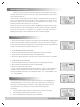
I:Left joystick
If transmitter is on Mode 1, this operates elevator (up and down)
and rudder (left and right).
If transmitter is on Mode 2, this operates throttle (up and down)
and rudder (left and right).
J:Right joystick
If transmitter is on Mode 1, this operates aileron (left and right)
and throttle (up and down).
If transmitter is on Mode 2, this operates aileron (left and right)
and elevator (up and down).
K:Left vertical trim tab
Mode 1: elevator trim; Model 2: throttle trim
L:Right vertical trim tab
Mode 1: throttle; Mode 2: elevator
M:Left horizontal trim tab
Mode 1: rudder; Mode 2: rudder
N:Right horizontal trim tab
Mode 1: aileron; Mode 2: aileron
O:Power switch
P:Neck strap hook
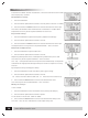
Q:Menu button
Enters into main menu
Enters into sub main menu
Enters into time page menu (release after
holding down the button for a few seconds)
R:Sub button
Enters into sub menu
Enters into sub sub-menu
Enters into time page menu (release after holding
down the button for a few seconds)
S:Y/UP
Validates selection
Increase data input
Puts channel in normal mode (release after
holding down the button for a few seconds)
T:Right button for selecting right in the display
U:N/Down
Cancels selection
Decrease data input
Puts channel in reverse mode (release after
holding down the button for a few seconds)
V:Left button for selecting left in the display
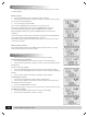
W:Steel handle for ease of carrying and transportation
X:Bind button to be used for establishing a connection
between the transmitter and receiver
Y:Plug port for simulator software connecting cable
Z:Battery bay for AA batteries
A1:Charging port to plug charging cable directly to
transmitter to charge batteries
NOTE: Only 9.6V Ni-MH battery packs can be
recharged.
X
W
Z
Y
A1
E
G
J
L
N
P
V
A
B
C
D
H
I
K
M
O
F
S
T
U
Q
R
www.blitzrcworks.com