442 EQ DUAL CHANNEL 15 BAND 2/3 OCTAVE GRAPHIC EQUALIZER 452 EQ SINGLE CHANNEL 31 BAND 1/3 OCTAVE GRAPHIC EQUALIZER USER’S GUIDE
EQUALIZER OVERVIEW – FEATURES AND GENERAL INFORMATION: MODEL 442 TWO CHANNEL 15 BAND 2/3 OCTAVE PRECISION GRAPHIC EQUALIZER The Model 442 features constant Q circuitry with a 3% center frequency accuracy. Special features include 60MM full range precision Sliders, LED metering, selectable range 6dB or 12dB, active balanced and unbalanced input/output connectors, RFI filters, variable input level control, passive bypass switch, clip level indicators, ground lift switch, and selectable line voltage switch.
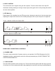
Balanced output requires using Pin 2 of the XLR or the tip of the 1/4” TRS as output Hi (+) and using pin 3 of the XLR or the ring of the 1/4” TRS as Lo (-). It does not require pin 1 or signal ground. The signal exists differentially between the two balanced leads. Ground is used only for shielding to prevent potential hum. Paralleling inputs and outputs may be accomplished by using any of the three connectors. Note: 1/4” TRS are normally used.
Here are some tips to help you with the initial set up: 1. Set channel levels to the center detent 0dB on the front panel. 2. Bypass the equalizer (Note: Select the bypass switch and press - the red LED is on.) 3. Set the frequency slide controls to the center detent or 0dB. 4. Select the 6dB range switch (green LED on). 5. Apply signal to the system. 6. Release the bypass switch, red LED off. 7. If the Clip LED is on you must turn down the input level control. 8.You may now start equalizing your system. 9.
2. FILTER LEVEL CONTROLS Each of these sliders controls the output level of each of the 31 (or 15) bandpass filters. The center detent position is grounded to assure flat response. 3. FILTER RANGE SWITCH & INDICATORS The gain range of the filter sliders is switchable (as a group) from +/- 6dB to + /-12dB for maximum boost/cut capability. At 6dB the green LED will illuminate and at 12dB the yellow LED will illuminate. 4.
8. LEVEL CONTROL This controls the level of signal coming into the equalizer. Turn this control down if the Clip LED illuminates steadily (meaning too strong an input signal). Unity gain can be set by turning this knob to its center detent position. 9. LED Metering Each channel of the equalizer has an LED array meter, showing its output level. Use the meter when adjusting the output level Control to aid in sending the proper level to your next piece of equipment.
nel. CAUTION: After checking the AC supply voltage, be sure that the correct fuse is in the fuse holder; 0.6Amp for 100-103VAC, as well for 220-240VAC. 12. AC VOLTAGE SELECTOR Set this slide switch to match your line voltage supply. CAUTION: For new installations and portable sound systems, or any situation in which the mains power is suspect, it is wise to confirm appropriate voltage and line polarity BEFORE connecting the instrument to power source. 13.
FOR UNBALANCED CONNECTIONS Use 1/4 inch tip-ring-sleeve or mono phone plug connectors or RCA phone jack connectors wired as follows: Phone Jack: Connection: tip = high ring = no connection sleeve = ground APPLICATIONS Graphic equalizers may be used wherever modification of the frequency contour of a sound system is needed. A graphic equalizer is a solution to any number of sound problems or creative urges.
WARRANTY INFORMATION Limited Warranty Applied Research and Technology will provide warranty and service for this unit in accordance with the following warrants: Applied Research and Technology (A R T) warrants to the original purchaser that this product and the components thereof will be free from defects in workmanship and materials for a period of three years from the date of purchase.
SERVICE The following information is provided in the unlikely event that your unit requires service. 1) Be sure that the unit is the cause of the problem. Check to make sure the unit has power supplied, all cables are connected correctly, and the cables themselves are in working condition. 2) If you find the unit to be at fault, write down a complete description of the problem, including how and when the problem occurs. Please write down a description of your complete setup before calling Customer Service.
SPECIFICATIONS EQUALIZER Bands Type Accuracy Travel Range INPUTS Type Connectors Impedance Maximum Level OUTPUTS Type Connectors Impedance Maximum Level OVERALL GAIN RANGE RFI filters Passive Bypass Switches Overload LED Threshold High Pass Filter Low Pass Filter Frequency Response THD + Noise IM Distortion (SMPTE) Signal to Noise Ratio Channel Separation Common Mode Rejection 1*31, 1/3 Octave ISO Spacing From 20Hz to 20kHz. (model 452) 2*15, 2/3 Octave ISO Spacing From 25Hz to 16kHz.
APPLIED RESEARCH & TECHNOLOGY 215 TREMONT STREET ROCHESTER, NEW YORK 14608 USA (585) 436-2720 – Voice (585) 436-3942 – Fax http://www.artproaudio.com E-mail: cserve@artproaudio.