CX311 Stereo 2-Way Active Crossover with Subwoofer Output SERVICE GUIDE
IMPORTANT SAFETY INSTRUCTIONS – READ FIRST This symbol, wherever it appears, alerts you to the presence of uninsulated dangerous voltages inside the enclosure that may be sufficient to constitute a risk of shock. This symbol, wherever it appears, alerts you to important operating and maintenance instructions in the accompanying literature. Please read the manual. Read instructions Retain these safety and operating instructions for future reference. Heed all warnings printed here and on the equipment.
TABLE OF CONTENTS IMPORTANT SAFETY INSTRUCTIONS – READ FIRST ............................................. 2 OVERVIEW .................................................................................................................... 4 Features ...........................................................................................................................................................4 INSTALLATION ...............................................................................................
OVERVIEW The ART CX311 Stereo 2-Way Active Crossover with Subwoofer Output offers a superb level of sound quality and its straightforward user interface gives you quick and easy access to all of its features. Designed for home, club, or DJ system applications or live sound reinforcement, the CX311 employs 24dB/ octave state-variable, fourth-order, Linkwitz-Riley filters. These filters guarantee inphase outputs at all frequencies.
INSTALLATION The ART CX311 may be used in a wide variety of applications and environments. Enclosed in a 1U (1.75 inches high) rack-mountable, all-steel enclosure, the unit is designed for continuous professional use. The depth is 5 inches. Mounting location is not critical. However, for greater reliability, we recommend that you not place the unit on top of power amps or other sources of heat. AC POWER HOOKUP The CX311 has an internal power supply designed to operate from 105 to 120VAC at 50/60Hz.
OPERATION FRONT PANEL CONTROLS POWER SWITCH The POWER switch applies and removes power to the unit. Make sure that all equipment after the CX311 is either off or the outputs are turned all the way down before turning the CX311 on or off. LOW OUTPUT LEVEL CONTROLS Each channel of the CX311 has a LOW OUTPUT LEVEL control. These controls are used to trim the output levels to the LOW OUTPUT jacks on the rear of the unit.
switches in the out (NORM) position. Pushing a button in (INVERT position) may be used to help correct audible phase-related problems. SUB OUTPUT LEVEL CONTROL This control is used to trim the audio output level to the SUBWOOFER OUTPUT jack on the rear of the unit. The subwoofer signal is used to provide extra bass via a mono subwoofer speaker in your system. This control covers the range of –30dB to +10dB of output gain trim, as indicated on the front panel. In most cases you would set it to 0dB.
APPLICATIONS Typical Setup For a stereo 2-way system, separate high frequency (horn or tweeter) and low frequency (bass) speaker cabinets are used for each channel (left and right) of the sound system and are driven by their own power amplifiers. The crossover is used to split each channel's signal into two frequency bands, which feed separate amplifiers. This delivers the proper frequencies to each speaker cabinet as well as allowing its associated amplifier to produce acoustic power more efficiently.
SERVICE PARTS PART # DESCRIPTION PART USAGE 100-5269-103 311-1027-216 311-1027-218 311-1027-217 Rocker power switch RSP POT SINGLE A100K RSP POT B50KX2 RSP pot C100K Dual 100-5242-101 SWT DPDT LATCHING level pots frequency pots Sub Freq SWITCHES INVERT/NORM 311-2004-101 311-2005-101 311-2006-101 311-2007-101 CON IEC POWER BLOCK W/FUSE AND SWT XFM Transformer TFX113EID1 SWT SPDT SLIDE SWITCH CON JACK 1/4" STEREO LOW CUT input and output jacks 311-2008-101 341-2009-101 MLD CAP POT BLK,GREY CAP w/b
FULL BILL OF MATERIALS Assembly ART PART# VENDOR PART# Description Location black-finish, silk printing QTY 3112002201 MPP00R0251 face plate FOR CX311 3112003201 MCC00B2921 top cover FOR ACX30/40 black finish 3112001201 MBP00R0251 chassis FOR CX311 black-finish, silk printing 1 3112004101 JA100312I8 IEC socket AC holder ACR-315-B 6P FUSE holder (115V / 230V) 1 1005269103 Rocker power swt 1 1001094110 FU31502D21 fuse 0.5A/250V 5*20mm Slow Blow 1 3422002101 KPCR081301 button round 7.
Main Ckt Board ART part# Vendor part # Description Location 1001162124 CE107012M2 100UF 1001038101 CC1010B4M2 100PF 1001162107 CE228033M1 2200UF 1001162104 CE106014M2 10UF 1001037105 CM1030B5J2 .01UF 1001037111 CM1040B5J2 .1UF CM2720B5J2 272PF 1001037109 CM4730B5J2 .047UF 1001037110 CM6830B5J2 .068UF 1001001301 RE810013F4 1K CAPACITORS EC 100UF/25V ±20% 2.5mm TAPING CC 100PF/50V ±20% 5.0mm TAPING EC 2200UF/35V±20% 7.5mm EC 10UF/50V ±20% 2.5mm TAPING PEI 0.01UF/100V ±5% 5.
ART part# Vendor part # 3112007101 JA406311L4 3412009101 JA700311L2 3111027218 VR0B503B1D 3111027216 VR5A104B1D 3111027217 VR7C104B1D 3112006101 SW02120002 3115242101 SW03220002 Description Location QTY JACKS EAR PHONE D=6.
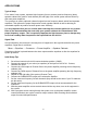
SCHEMATICS 1 2 3 4 5 6 8 7 C3 IN J2 100P R3 100K 250Hz -- 6KHz 2 R19 103 U2A 4 7 U1B 6 R7 U3B 5 2068DD R18 2K1 7 U4A 3 R21 2K1 2068DD +15V 6 2068DD 1 R23 VR2 A100K 7 U4B 5 VR1C B50K VR1A B50K R15 10K R17 2K49 10K R6 R41 10K 10U/50V 2068DD PHASE R29 HI OUT R32 100K 10k R30 10k R25 10K C35 100P C15 R34 10K VR3 A100K 100P 100K R36 R35 10K R22 10K B50K 220R R31 7 U5B 6 100P 2068DD R10K J3 C10 5 SW1 +15V VR1D VR1B B50K R9 15K 10K 2 1 U3A 3 R16
Notes 14
WARRANTY INFORMATION Limited Warranty Applied Research and Technology will provide warranty and service for this unit in accordance with the following warrants: Applied Research and Technology, (ART) warrants to the original purchaser that this product and the components thereof will be free from defects in workmanship and materials for a period of three years from the date of purchase.
SERVICE The following information is provided in the unlikely event that your unit requires service. 1. Be sure that the unit is the cause of the problem. Check to make sure that the unit has power supplied, that all cables are connected correctly, and that the cables themselves are in working condition. You may want to consult with your dealer for assistance in troubleshooting or testing your particular configuration. 2. If you believe that the ART unit is at fault, go to www.artproaudio.com.
SPECIFICATIONS Input Connections Output Connections XLR, 1/4” TRS, balanced 1/4” TS, unbalanced Frequency Response 10Hz to 40kHz, +0/-0.
www.artproaudio.com E-mail: support@artproaudio.com © 2010 Applied Research & Technology CX311 V1.