DIGITAL MPA II™ ART DIGITAL MPA II™ Microphone Preamplifier USER’S GUIDE
IMPORTANT SAFETY INSTRUCTIONS – READ FIRST This symbol, wherever it appears, alerts you to the presence of uninsulated dangerous voltage inside the enclosure. Voltage that may be sufficient to constitute a risk of shock. This symbol, wherever it appears, alerts you to important operating and maintenance instructions in the accompanying literature. Please read manual. Read instructions: Retain these safety and operating instructions for future reference. Heed all warnings printed here and on the equipment.
IMPORTANT SAFETY INSTRUCTIONS – READ FIRST ......................................................... II DIGITAL MPA II OVERVIEW – FEATURES AND GENERAL INFORMATION: ...................... 1 FRONT PANEL CONNECTIONS AND CONTROLS ................................................................ 3 Input Gain control ..................................................................................................................................... 3 Input Impedance control ........................................
DIGITAL MPA II OVERVIEW – FEATURES AND GENERAL INFORMATION: The ART DIGITAL MPA II microphone preamplifier features a new low noise, high performance preamplification circuitry, designed for superior audio fidelity. Building upon the quality and success of great sounding products like the Pro MPA and MPA GOLD, ART engineers set out to develop the next generation of professional microphone preamplifier.
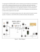
The signal path of the DIGITAL MPA II consists of a discrete class A microphone pre-amp followed by a Low Cut Filter, a balanced differential tube circuit with a 20dB Gain switch and then the phase switch. At this point the signal passes to both the analog output and the Insert jacks. The insert jacks allow processing of the signal before its’ level is adjusted by the Digital Level control and passed to the A/D.
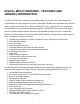
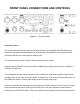
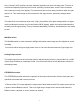
FRONT PANEL CONNECTIONS AND CONTROLS Figure 2 – Front controls Input Gain control This control optimizes the input signal level before the tube gain is applied. Both Microphone and Instrument input gains remain the same and are affected by this adjustment. Input gain can be adjusted from 0dB (for line level signals) to 40dB of gain. The analog meters are used to see the effects of the input gain setting.
with the DIGITAL MPA II for more detailed instructions on setting the Input Gain control for the best results. Input Impedance control This knob controls the Mic/line input amplifier impedance. This function allows variable voicing of any microphone. Refer to the application section titled “Adjusting the Input Impedance” for more information on making the most of this function. The ¼” instrument input is NOT affected by this control, and remains high (>1M Ohm) impedance.
Phantom switch Phantom power on the microphone input is turned on and off with this switch. Depressing the switch will power condenser microphones and other 48volt phantom powered devices. Phantom power is supplied to pins 2 and 3 of the input jack. NOTE: 1) Dynamic microphones are NOT affected by Phantom power, although it should be turned off when using dynamic microphones or line level inputs. 2) Although the 48volt phantom power ramps up and down slowly it may still create a pop.
In the “Normal” (OUT) position, the tube distortion gradually rises until it smoothly clips. The tube is run almost completely open-loop in this mode, providing a musical tube “crunch” when overdriven with a natural recovery from clipping. The tube section can be more easily overdriven when the gain switch is in. This mode brings out the harmonics in the input sources, particularly stringed instruments. The tube circuit runs extremely clean in the “High” (IN) position of the plate voltage switch.
When the switch is in the “Dual” position the output controls act on only their respective channels. +4/-10 switch (rear panel) The +4/-10 switch is used to set the output level of the DIGITAL MPA II for the appropriate system levels. This feature allows you to match 0 VU on the meters of the DIGITAL MPA II and your mixer or other equipment. When depressed, 0 VU on the output meter corresponds to +4dBu on the outputs. In –10 mode, the output level measures –10dBV.
As the Digital Level control is used refer to the Digital Level LED meter which indicates both peak and average level present at the A/D converter input. This meter helps you get the perfect level adjustment and avoid clipping the A/D. Refer to the section titled “Obtaining the perfect digital level setting” for more detail on the operation and use of these features. Sample Rate control The Sample rate knob determines both the output sample rate of the DIGITAL MPA II as well as the dither.
sample rates, indicating the fraction of a second it takes to settle to the new rate. This is normal). NOTE: When using the ADAT Input as a sync source, the maximum sample rate is limited to about 50KHz. Dither settings The DIGITAL MPA II possesses a 24-bit A/D converter. When the output of the unit goes off to a system that can handle only 16 bit data, the 8 least significant bits of data are ignored (truncated). This leaves the sound with gritty “digital” sounding signals at very low levels.
Front Panel connections Instrument Inputs The ¼” jacks on the front panel serve as an instrument input. The input impedance is always >1M Ohm and the gain can be adjusted by the Input gain control. The maximum input signal level is +17dBu (5Vrms) @ minimum input gain. When you plug into this jack it DISABLES the balanced input on the rear of the unit. This feature allows you to keep the rear input patched in, and use the instrument input to switch to a different source.
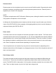
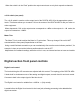
Rear Panel connections Figure 4 – Rear connections Balanced Inputs The DIGITAL MPA II’s XLR connectors follow the AES standard of Pin 1 = Ground, Pin 2 = Hot (+), Pin 3 = Cold (-). The Balanced inputs have an input impedance that is variable from 150 to 3K Ohms via the front panel control. The Maximum input level is +19dBu balanced and +17dBu unbalanced. Balanced Outputs The DIGITAL MPA II ‘s flexible active balanced outputs are available on both ¼” and cannon connectors.
Insert jacks The insert jacks are used to process the audio passed on to the A/D converter. The Insert Jacks are wired: Tip = Input, Ring = Output, Sleeve = Ground. The input impedance is 10K Ohm and the output impedance is 1K Ohm. The minimum input signal required to drive the A/D to clip is +12dBu (3V RMS) Wordclock jacks The DIGITAL MPA II offers Wordclock input on a BNC connectors. A 5V logic level signal is required to drive the digital clock circuitry.
Using the optical output in S/PDIF is recommended over the coax output, as it is the most robust and reliable of all the digital outputs. S/PDIF output The S/PDIF coax connector allows the DIGITAL MPA II to connect to a wide range of consumer and professional equipment. This output is .5V p-p (when connected) isolated from ground, and has a 75 Ohm impedance.
DIGITAL MPA II OPERATING INSTRUCTIONS Obtaining the best noise performance with the DIGITAL MPA II Start by turning down the Input Gain knob and centering the Analog Output knob. Set the +20dB switch , Plate Voltage1 switch and the Stereo/ Dual mode switch in the "out" position. The analog VU meter will now indicate how much tube headroom there is. Increase the Input Level knob until the analog VU meter reads above –10dB.
Dynamic microphones are affected as much as phantom powered units. We provide a continuously variable impedance control to allow you to fine-tune the voicing, finding the perfect interaction between microphone and pre-amp. Start by setting the centering the Input Impedance knob. This provides a 600-Ohm load. Lower impedance loads will reject more noise picked up by cabling, and dampen microphone resonance. Higher impedance settings provide a more “open” sound. Lower impedances tend to focus the sound more.
Setting the Tube Plate Voltage The DIGITAL MPA II allows the user select between one of two vastly different tube bias and power supply levels. The transition between either setting is smooth and quiet and the gain variation is minimal. NOTE: It takes 15-30 seconds for the tube circuit to fully transition between either mode. During this time, the unit passes a signal and the only noticeable change is a slight increase in level in the “HIGH” setting.
Using the Mid/Side mode The DIGITAL MPA II is designed for stereo operation using the Mid/Side switch and two microphones. One of the mics needs to have a figure-8 pickup pattern. Start by aligning two mics 90 degrees apart. Connect the mic facing front (with an omni-directional or cardiod pickup pattern) to CH1. Face the front of the figure-8 pickup mic to the left side and connect it to the CH2 input (refer to figure 4). Depress the M/S switch and center both of the Output Gain controls.
WARRANTY INFORMATION Limited Warranty Applied Research and Technology will provide warranty and service for this unit in accordance with the following warrants: Applied Research and Technology (A R T) warrants to the original purchaser that this product and the components thereof will be free from defects in workmanship and materials for a period of three years from the date of purchase.
SERVICE The following information is provided in the unlikely event that your unit requires service. 1) Be sure that the unit is the cause of the problem. Check to make sure the unit has power, all cables are connected correctly, and the cables themselves are in working condition. You may want to consult with your dealer for assistance in troubleshooting or testing your particular configuration. 2) If you believe the ART unit is at fault, go to www.artproaudio.com.
DIGITAL MPA II SPECIFICATIONS Analog Section: Frequency Response.................................. 15Hz to 48 kHz (+0, -1dB) @ normal plate voltage 15Hz to 120 kHz (+0, -1dB) @ high plate voltage Dynamic range:........................................... >110dB (“A” weighted) CMRR: ........................................................ >90dB THD: ........................................................... <0.005% (typical) Equivalent Input Noise:...............................
www.artproaudio.com E-mail: cserve@artproaudio.