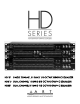
HD131 SINGLE CHANNEL 31 BAND 1/3 OCTAVE GRAPHIC EQUALIZER HD215 DUAL CHANNEL 15 BAND 2/3 OCTAVE GRAPHIC EQUALIZER HD231 DUAL CHANNEL 31 BAND 1/3 OCTAVE GRAPHIC EQUALIZER
IMPORTANT SAFETY INSTRUCTION – READ FIRST This symbol, whenever it appears, alerts you to the presence of uninsulated dangerous voltage inside the enclosure-voltage that may be sufficient to constitute a risk of shock. This symbol, wherever it appears, alerts you to important operating and maintenance instructions in the accompanying literature. Please Read manual. Read instructions: Retain these safety and operating instructions for future reference. Heed all warnings printed here and on the equipment.
The new ART HD-Series of Precision Graphic Equalizers have been designed and engineered to exceed extremely high standards for audio performance and functionality. These innovative, high-quality equalizers are perfect for virtually any audio application where precision frequency tailoring, reliable performance, rugged design and extremely silent processing is of the utmost priority.
GENERAL INFORMATION Congratulations on the purchase of your new ART equalizer. This professional equalizer is perfect for virtually any audio application where frequency tailoring is needed.
EUROBLOCK CONNECTIONS Insert the wires, and then snug down with the set screw. The entire barrier strip can be removed for quick service without disconnecting the individual wires. SIGNAL LEVELS Signal levels from -10dBu to +4dBu are considered normal with maximum levels of approximately +22dBu balanced or +16dBu unbalanced. Do not connect microphones directly to the equalizer. Most Microphones, as well as instrument pickups, require a preamp to get the signal level up to a line level.
OPERATING INSTRUCTIONS Before starting to equalize your sound system there is some information you should know and procedures you should follow. Your equalizer is equipped with a bypass switch. The bypass switch, when activated, lights the bypass LED and cancels all equalization settings while allowing signal to flow directly through the unit at unity gain. Also included is a range selection switch with LED indicators, +/-6dB = green, +/-12dB = yellow.
FRONT PANEL CONTROLS 1. POWER SWITCH To turn the equalizer ON or OFF, press the upper or lower portion of this button. CAUTION: Always turn on your equalizer BEFORE your power amplifiers are turned on, and always turn off your equalizer AFTER your power amplifiers have been turned off. 2. FILTER LEVEL CONTROLS Each of these sliders controls the signal level of each of the 31 (or 15) bandpass filters. A detent at the center position helps center the controls for a flat response. 3.
Clip Indicator: - This red LED illuminates if any section of the equalizer is near clipping. Occasional flickering of this LED is acceptable, but if it remains on more than intermittently you should reduce the output level of the preceding equipment or, if that is not possible, turn down the equalizer’s level control to avoid audible distortion. 5.
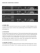
REAR PANEL CONNECTORS & CONTROLS 8. POWER CORD This cord is used to connect the AC power source to your equalizer. CAUTION: Equipment for USA installation includes a power cord with a three pin polarized plug. DO NOT REMOVE THE CENTER GROUNDING PIN. 9. FUSE HOLDER This fuse holder contains the AC primary fuse. This fuse should be replaced with the same type fuse if it is blown. If they continuously blow, stop replacing fuses and refer servicing to qualified personnel.
11. INPUT/OUTPUT CONNECTORS 1/4 TRS The TRS (Tip Ring Sleeve) connector is balanced and wired as Tip = High (+), Ring = Low (-), and Sleeve = Ground. XLR The XLR input connector is balanced and wired as Pin 2=High (+), Pin 3=Low (-), and Pin 1=Ground. EURO BLOCK HD131 HD 215, HD231 CAUTION: Only one input option should be chosen for audio connection at the same time.
APPLICATIONS Graphic equalizers may be used wherever modification of the frequency contour of a sound system is needed. A graphic equalizer is a solution to any number of sound problems or creative urges.
WARRANTY INFORMATION Limited Warranty Applied Research and Technology will provide warranty and service for this unit in accordance with the following warrants: Applied Research and Technology, (A R T) warrants to the original purchaser that this product and the components thereof will be free from defects in workmanship and materials for a period of one year from the date of purchase.
SERVICE The following information is provided in the unlikely event that your unit requires service. 1) Be sure that the unit is the cause of the problem. Check to make sure the unit has power supplied, all cables are connected correctly, and the cables themselves are in working condition. 2) If you find the unit to be at fault, write down a complete description of the problem, including how and when the problem occurs. Please write down a description of your complete setup before calling Customer Service.
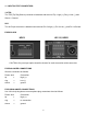
SPECIFICATIONS: EQUALIZER Bands Type / Accuracy Travel Range Overall Gain Range INPUTS Type Connectors Impedance Maximum Level OUTPUTS Type Connectors Impedance Maximum Level RFI filters Passive Bypass Switches Overload LED Threshold High Pass Filter Low Pass Filter Frequency Response THD + Noise IM Distortion (SMPTE) Signal to Noise Ratio Headroom Dynamic Range Channel Separation Common Mode Rejection 2 x 15, 2/3 Octave, ISO Spacing (HD215) 1 x 31, 1/3 Octave, ISO Spacing (HD131) 2 x 31, 1/3 Octave, ISO S
APPLIED RESEARCH & TECHNOLOGY 215 TREMONT STREET ROCHESTER, NEW YORK 14608 USA (585) 436-2720 – Voice (585) 436-3942 – Fax www.artproaudio.com E-mail: cserve@artproaudio.