
User`s manual


4
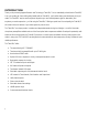
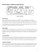
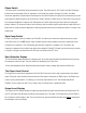
FRONT PANEL CONTROLS & INDICATORS
Figure 1 - Front view
Gain Control
The Gain control sets the amount of input gain of the Tube MP/C. Turn the control clockwise to increase gain and
counterclockwise to decrease gain. Selection of the gain range is made with the +20dB gain switch. You may control two
ranges of gain with this control, +20 to +60dB and +0 to +40dB. When setting the Gain control, refer to the four segment
Tube Drive display for a visual reference to the Tube MP/C’s internal signal levels (applied gain). Hint: the “sweet” spot for
the Tube MP/C is when the second warm LED in the Tube Drive array is lit.
Gain Switch
Use the Gain switch to set the range of the Gain control. When the switch is in the out (0db) position the gain range is +0 to
+40dB. Depressing the switch adds 20dB of gain. With the switch in, the gain range is +20 to +60dB. With most microphone
applications you’ll find using the Tube MP/C with the +20dB gain switch in is needed. Use the setting that best fits your
application.
Low Cut Switch
The LOW CUT switch rolls off the response to signals lower than 70Hz. This helps to cut out low frequency rumble, wind
noise, and all types of very low frequency energy before it is amplified. When recording, this allows you to get more gain
before clipping the preamp, recorder, or computer and in a live situation you get more gain before clipping your amp.
Tube Drive Display
Four LEDs display how the tube gain is affecting the input signal. These LEDs are calibrated with the tube circuitry to give
you an accurate representation of the tube’s output signal (Note: these LEDs measure the signal level before the output
level control). Use this meter as a visual aid for setting the Gain level. The first LED is labeled “CLEAN”. The tube is