
User Guide


- 5 -
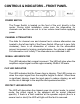
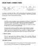
CONTROLS & INDICATORS – FRONT PANEL
POWER SWITCH
The Power Switch is located on the front of the unit, directly in the
center. During initial installation, make sure the attenuators for
channels one and two are set to a low volume level before applying
power.
CHANNEL ATTENUATORS
The dials for channel one and channel two’s volume attenuators are
located to the left and right of the Power Switch. When set to zero (fully
clockwise), there is no attenuation of volume. As the attenuation
amount increases by turning counterclockwise, the volume is reduced.
Full attenuation is at -infinity. The attenuators are calibrated in dB.
SIGNAL LED INDICATOR
This LED indicates that a signal is present. The LED will glow when the
amplifiers output signal is within approximately 30dB of full scale.
CLIP LED INDICATOR
This LED indicates that the Power Amp is clipping. This LED comes on
when the output signal from the amplifier begins to distort. When there
is significant clipping, lower the input gains to reduce clipping, as well
as the risk of damage to the amplifier and speakers/monitors.
PROTECT LED INDICATOR
The LED will glow when the channel goes into protect mode. In protect
mode, the output signal to the speakers will be muted (channel
specific). If there is a fault condition at the speaker outputs (due to a
severe load or short) the LED will light until the fault is removed.