Tubeopto 8™ 8-CHANNEL TUBE MICROPHONE PREAMPLIFIER / OPTICAL INTERFACE USER’S GUIDE
IMPORTANT SAFETY INSTRUCTIONS – READ FIRST This symbol, wherever it appears, alerts you to the presence of uninsulated dangerous voltage inside the enclosure. Voltage that may be sufficient to constitute a risk of shock. This symbol, wherever it appears, alerts you to important operating and maintenance instructions in the accompanying literature. Please read manual. Read instructions: Retain these safety and operating instructions for future reference.
The ART Tubeopto 8™ 8-Channel Tube Microphone Preamplifier Optical Interface IMPORTANT SAFETY INSTRUCTIONS – READ FIRST .............................................. II INTRODUCTION..........................................................................................................1 INSTALLATION...........................................................................................................1 AC Power Hookup......................................................................................
INTRODUCTION The Tubeopto 8™ is the ideal Eight Channel input/output expander for any ADAT Lightpipe equipped audio interface, direct-to-disc recorder or DAW. Eight high quality second-generation discrete class–A vacuum tube microphone preamps are packaged in a single rack space unit with eight channel 24-bit digital I/O. The mic preamps drive internal high quality A/D converters and a standard ADAT Lightpipe digital interface.
CONTROLS and JACKS FRONT PANEL Instrument Input The 1/4” TS jack on the front panel provides a high impedance unbalanced input, and when used, automatically switches off the mic pre-amp section. (The rear combo jack’s 1/4” TRS balanced input is lower impedance and is part of the mic pre-amp. The rear jack is not intended to be used with high impedance microphones or instruments.) NOTE: The PAD switch is disabled and DOES NOT affect gain when using the Instrument input.
+48V Switches These switches provide phantom power to each set of four XLR inputs. Use phantom power only when the microphone you are using requires it. Doing so will extend the life of the Tubeopto 8™ as well as reduce the possibility of a shock hazard. Phase Switch This switch selects the output phase of each channel. There is a 180-degree phase inversion through the channel when the switch is lit. Low Cut Switch This switch inserts an 80Hz 6dB/Oct. Low-Cut filter into the signal path.
Sample Rate LEDs This display indicates the rate and source of the A/D converter sample rate. (The D/A sample rate is independent of this setting as it always slaves to the incoming ADAT data). The ADAT LED will flash if there is no incoming ADAT data, or a data error. This is true for every sample rate mode (not just ADAT). Selecting Wordclock will light the red Wordclock LED and this LED will flash if the Tubeopto 8™ cannot use this input as a sync source.
Wordclock Input and Thru Jacks The Wordclock input is used to externally sync the Tubeopto 8™ to a master clock source. The BNC Wordclock Input jack is connected directly to the BNC Wordclock Thru jack, providing the ability to loop through the Tubeopto 8™ and connect other devices to the wordclock sync source, saving the use of a BNC T–adapter. FIGURE 4 - Block Diagram The Wordclock input is high impedance thus leaving the wordclock connection unterminated.
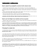
HARDWARE OPERATION How to adjust the preamplifier controls for the lowest noise Start with the Gain and Output knobs centered, and the Pad switch in. This provides about 20dB of gain. Increase the Gain control until the Clip LED in the meter just barely comes on during the loudest peaks in level, and then back off the control slightly from that point. (The Clip LED should come on occasionally at most.
Using the Wordclock input The Tubeopto 8™ can be used in both simple and complex systems. The simplest system would consist of the Tubeopto 8™ and a single ADAT interface. As multiple digital devices are added to a system, master/slave sample rate timing issues can degrade system audio performance.
APPLICATIONS Typical applications The Tubeopto 8™ makes an ideal addition to any ADAT compatible Digidesign interface running ProTools software. Simply connect the ADAT Output from the Tubeopto 8™ to the Optical In of the Digi product and connect a 75 Ohm BNC cable between the Digi Wordclock Out and the Wordclock In on the Tubeopto 8™. Set the Tubeopto 8™ for Wordclock sync and you have just added 8 more high quality preamp channels to your ProTools setup.
Troubleshooting Here is a list of things to check first: 1) Check the power switch. It should be lit red (when the switch is depressed of course). If not lit red, check the power connections and fuse on the rear panel. 2) Check the Sample Rate lights. There should always be at least one lit. On power up, they first ALL light then light one at a time from 44K to Wordclock and finally settle to the current sample rate.
WARRANTY INFORMATION Limited Warranty: Applied Research and Technology will provide warranty and service for this unit in accordance with the following warrants: Applied Research and Technology, (A R T) warrants to the original purchaser that this product and the components thereof will be free from defects in workmanship and materials for a period of three years from the date of purchase.
SERVICE The following information is provided in the unlikely event that your unit requires service. 1) Be sure that the unit is the cause of the problem. Check to make sure the unit has power, all cables are connected correctly, and the cables themselves are in working condition. You may want to consult with your dealer for assistance in troubleshooting or testing your particular configuration. 2) If you believe the ART unit is at fault, go to www.artproaudio.com.
Tubeopto 8™ SPECIFICATIONS Input Impedance Mic..............................................................................................6.4K Ohm Line ............................................................................................20K Ohm Instrument ..................................................................................2.5M Ohm Output Impedance Balanced outputs........................................................................
www.artproaudio.com E-mail: cserve@artproaudio.