Sensor Controlled Robot Assembly Instructions is a registered trademark of Artec Co., Ltd. in multiple countries including Japan, South Korea, Canada, and the USA.
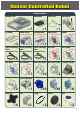
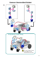
Sensor Controlled Robot Components Studuino Unit ×1 DC Motor Sound Sensor Sound Sensor ×2 Sensor Connecting Cable (three-wire 15 cm) Blue Sensor Connecting Cable (three-wire 30 cm) LED (white) White ×1 Triangle A (clear) Half A (light gray) ×2 ×1 Hub ×4 Accelerometer Accelerometer Sensor Connecting Cable (four-wire 50 cm) Light Sensor Half B (blue) LED (red) Buzzer Red Buzzer ×1 LED (green) Green ×1 ×1 Basic Cube (clear) Triangle A (gray) ×2 ×4 Half C (light aqua) ×10 Half
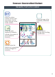
Sensor Controlled Robot Assembly Instruction Labels Shows the sticker number used for each servomotor. Use the motor with the correct sticker number. Sensor Controlled Robot Assembling the Head ×1 ×1 Shows the parts needed for assembly. Indicates the number of parts needed for assembly. ×2 ×2 ×3 ×12 ×2 ×6 ×1 ① ② Indicates when the direction of a component must be changed for assembly. Shows an image of the completely assembled item. Indicates tips or warnings when building a specific item.
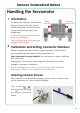
Sensor Controlled Robot Handling the Servomotor 1 Orientation The photo to the right shows the servomotor facing you. There are two shafts, the one Wider (drive shaft) Narrower (movable shaft) with the wider space is the drive shaft and the one with the narrower space is the movable shaft. ★ When turning the drive shaft by hand, do so very slowly and gently. Excessive pressure when turning may cause damage to the servomotor.
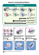
Sensor Controlled Robot Preparation ×1 ×1 ×1 ×1 ×1 ×1 ×1 ×1 ×6 (three-wire 15 cm) Sensor Connecting Cable ×1 Sensor Connecting Cable (three-wire 30 cm) ×1 (four-wire 50 cm) Sensor Connecting Cable Connect the sensor connecting cable to each sensor.
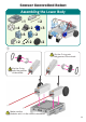
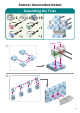
Sensor Controlled Robot Assembling the Lower Body ×1 ×4 ×2 ×2 ×6 ×2 ×3 ×2 ×2 ×2 ① Slip the O-ring onto the grooves of the wheel. Slip the O-ring onto the grooves of the wheel.
Sensor Controlled Robot ② ③ 07
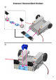
Sensor Controlled Robot ④ Connect to M1. M1 Make sure the cables are inserted correctly! M1 ⑤ Connect to M2.
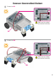
Sensor Controlled Robot ⑥ Co mp l et ed L o w e r B ody DC motor cables should be arranged on the outside of the car body.
Sensor Controlled Robot Assembling the Torso ×2 ① ×2 ×15 ×1 ×1 ×1 ×1 Green Red ② 10
Sensor Controlled Robot ③ ④ ② ① ⑤ Blue White 11
Sensor Controlled Robot ⑦ Co mp l et ed Tor so 12
Sensor Controlled Robot Assembling the Right Arm ×1 ×2 ×2 ×1 ×2 ×1 ① Wider 13
Sensor Controlled Robot Assembling the Left Arm ×1 ×2 ×1 ×1 ×2 ×1 ×1 ① Wider Buzzer 14
Sensor Controlled Robot Assembling the Head ×1 ×2 ×2 ×3 ×12 ×2 ×6 ×1 ① ② Wider ③ 15
Sensor Controlled Robot ④ ⑤ Sound Sensor ⑥ 16
Sensor Controlled Robot ⑦ ⑧ 17
Sensor Controlled Robot ⑨ C o m p l et ed H ea d 18
Sensor Controlled Robot Putting the Parts Together ① Connect the cable from servomotor to its corresponding place on your Studuino unit.
Sensor Controlled Robot ② Connect the cable from servomotor to its corresponding place on your Studuino unit. Make sure the cables are inserted correctly! ③ Connect the cable from the buzzer to A4.
Sensor Controlled Robot from the LEDs (red, green) on the torso should pass between the arms ④ Cables and lower body. ⑤ Lift the left arm and attach the torso. Lower the left arm after attaching the torso.
Sensor Controlled Robot ⑥ Connect the cable from the green LED to A3. A3 Make sure the cables are inserted correctly! ⑦ Connect the cable from the red LED to A2.
Sensor Controlled Robot ⑧ Arrange the torso LED cables (white, blue) as shown below. Connect the white LED cable to A0 and the blue LED cable to A1.
Sensor Controlled Robot ⑨ Attach the head to the torso. Gently turn the studs on the servomotors for both arms upward. Make sure not to pinch any cables between blocks.
Sensor Controlled Robot ⑩ Connect the cable from servomotor to its corresponding place on your Studuino unit. Connect the sound sensor to A6.
Sensor Controlled Robot Assembling the Battery Box ×1 ×1 ×1 ×1 ① Insert the battery box between the lower body and the torso. + - POWER You should see the battery box switch here.
Sensor Controlled Robot ② Do not connect the Half A (light gray) stud to the main body.
Sensor Controlled Robot Attaching the Light Sensor ×1 Connect the light sensor to the body and its cable to A7.
Sensor Controlled Robot Replacing the Batteries ① ② ③ ④ ⑤ Use a screwdriver (Phillips #1) to open. Insert batteries in the correct polarity. Put the lid of the battery box back in place.
Sensor Controlled Robot Completed Sensor Controlled Robot Before operating your robot, check the Assembly Instructions again to confirm your robot has been assembled correctly.
Sensor Controlled Robot 下半 身 の 完Operating 成 Your Sensor Controlled Robot Install the software from the URL below to setup the Studuino Programming Environment. ★ Proceed to Step 1 when software installation is complete. http://www.artec-kk.co.jp/studuino/ ① ② Connect the USB cable to the PC and the Studuino unit. Refer to 1.3. About Studuino in Studuino Programming Environment Manual for more details. Download the program file SensorControlledRobot.ipd_1 from the URL below in the ArtecRobo section.
Sensor Controlled Robot Immediately turn the switch to off if your robot does not begin working as shown in the picture below. Not doing so may damage the servomotor. If your robot does not move, the servomotor may be in the wrong position or the blocks may be improperly connected. Re-read the Assembly Instructions to make sure that your robot has been assembled correctly. ⑥ Turn the switch of the battery box on and your robot will start playing music and moving.
Sensor Controlled Robot Sensor Calibration Some sensors may not function properly after you run the program for the first time. If the sensors are malfunctioning, calibrate the sensor settings. Click the corresponding sensor and you will see a box to adjust the range settings. Drag the mouse left or right to adjust the range settings. Refer to the Condition Icon sections in 4.4. The Attribute Field of the Studuino Programming Environment Manual for more details.
Sensor Controlled Robot Using an Accelerometer with Your Robot ×1 ×1 ① Accelerometer ② Unplug the buzzer from A4 and connect the accelerometer cable to A4/A5. A4 A5 Connect to the accelerometer to both A4 and A5.
Sensor Controlled Robot Completed Robot with Accelerometer Before operating your robot, check the Assembly Instructions again to confirm your robot has been assembled correctly.
Sensor Controlled Robot 下半 身 の 完成 Using the Accelerometer ① Transfer SensorControlledRobot_2.ipd to your Studuino. See page 31 of this guide for instructions on how to transfer data. ② Turn the switch of the battery box on and tilt the accelerometer to control your robot. Hold the controller parallel to the ground and tilt it to make your Sensor Controlled Robot move.
Sensor Controlled Robot Sensor Calibration Some sensors may not function properly after you run the program for the first time. If the sensors are malfunctioning, calibrate the sensor settings. Click the corresponding sensor and you will see a box to adjust the range settings. Drag the mouse left or right to adjust the range settings. Refer to the Condition Icon sections in 4.4. The Attribute Field of the Studuino Programming Environment Manual for more details.