Doggy Robot Assembly Instructions is a registered trademark of Artec Co., Ltd. in multiple countries including Japan, South Korea, Canada, and the USA.
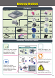
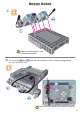
Doggy Robot Contents LED (red) Studuino Unit ×1 Basic Cube (white) Servomotor Battery Box USB Cable ×1 Sensor Connecting Cable (three-wire 15 cm) Sound Sensor ×3 ×3 ×1 Sound Sensor ×1 Triangle A (gray) Half B (blue) Half D (aqua) Red ×1 ×9 ×4 ×9 ×14 Reflective Infrared Sensor Basic Cube (clear) Triangle A (clear) Half C (light aqua) Rotor Axis C IR Photo reflector ×1 ×2 ×2 ×38 ×8 Assembly Instruction Labels ×1 Shows the parts needed for assembly.
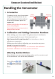
Sensor Controlled Robot Handling the Servomotor 1 Orientation The photo to the right shows the servomotor facing you. There are two shafts, the one Wider (drive shaft) Narrower (movable shaft) with the wider space is the drive shaft and the one with the narrower space is the movable shaft. ★ When turning the drive shaft by hand, do so very slowly and gently. Excessive pressure when turning may cause damage to the servomotor.
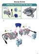
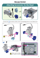
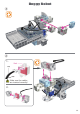
Doggy Robot Attaching Servomotor for the Legs ×2 ×1 ×1 ① W Wider W Wider 04
Doggy Robot ② Make sure the Studuino unit is inserted correctly! ③ Connect the and on your Studuino unit.
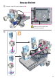
Doggy Robot Attaching Servomotor for the Head ×1 ×1 Connect the ×3 servomotor cables to their corresponding places on your Studuino unit. 1. 2.
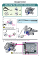
Doggy Robot Attaching the Reflective Infrared Sensor ×1 ×1 ×1 ×1 ① 1. Sensor Connecting Cable Gray Circuit board side Sensor side Black IR Photo reflector Make sure the cables are inserted correctly! 2. ② Connect the cables from the reflective infrared sensor to A5.
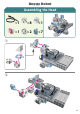
Doggy Robot Assembling the Head ×1 ×8 ×1 ×1 ×2 ×7 ① ② 08
Doggy Robot ③ ④ 1. Red Gray Black Make sure the cables are inserted correctly! 2.
Doggy Robot ⑤ Connect the LED (red) cables to A4.
Doggy Robot Assembling the Torso ×5 ×6 ① 11
Doggy Robot ② ③ 12
Doggy Robot ④ ⑤ 13
Doggy Robot Assembling the Torso ×8 ×2 ×2 ① 14
Doggy Robot ② 15
Doggy Robot Assembling the Torso ×12 ×2 ×2 ×4 ① 16
Doggy Robot ② 17
Doggy Robot Assembling the Torso ×10 ① ×4 ② 18
Doggy Robot Assembling the Torso ×2 ×1 ×1 Connect the sound sensor cables to A6.
Doggy Robot Installing the Battery Box ① ② Connect the cable from the battery box to the POWER section. You should see the battery box switch here. − + POWER Replacing the Batteries ① ③ ② Use a screwdriver (Phillips #1) to open. Insert batteries in the correct polarity. Put the lid of the battery box back in place.
Doggy Robot Completed Doggy Robot Be cautious of cables that could become entangled in the moving parts of the motor and cause the robot to disconnect. Take care when arranging cables. Before operating your robot, check the Assembly Instructions again to confirm your robot has been assembled correctly.
Doggy Robot Operating Your Doggy Robot Install the software from the URL below to setup the Studuino Programming Environment. ★ Proceed to Step 1 when software installation is complete. http://www.artec-kk.co.jp/studuino/ ① ② Connect the USB cable to the PC and the Studuino unit. Refer to 1.3. About Studuino in Studuino Programming Environment Manual for more details. Download the program file DoggyRobot.ipd from the URL below in the ArtecRobo section. http://www.artec-kk.co.
Doggy Robot Operating Your Doggy Robot ⑥ Turn the switch of the battery box on and your robot will start walking. Immediately turn the switch to off if your robot does not begin walking as shown in the picture below. Not doing so may damage the servomotor. If your robot does not move, the servomotor may be in the wrong position or the blocks may be improperly connected. Re-read the Assembly Instructions to make sure that your robot has been assembled correctly.
Doggy Robot Sensor Calibration Some sensors may not function properly after you run the program for the first time. If the sensors are malfunctioning, calibrate the sensor settings. Click the Submenu 1 tab to calibrate the sensors and you will see a box to adjust the range settings. Drag the mouse left or right to adjust the range settings. Refer to the Sensor Condition Icon sections in 4.4. The Attribute Field of the Studuino Programming Environment Manual for more details.