
Specifications


Introduction
Quest Installation Procedure
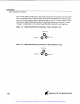
Screw in the bushing for one end of the tube labeled
"Man.
Del." to the remaining red
bulk head fitting located on the front face of the upper Reactor Assembly. This will be
the lower port of a set of
2
mounted together. Screw the other end of the tube into the
female threaded port on the Upper Manifold at the right of the "triangle of ports (see
diagram)."
Repeat the tubing installation for the other side of the Quest Reactor Unit.
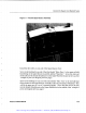
Install the Glass Waste Tank
Unpack the rectangular Glass Waste Tank from the box.
On the Quest Reactor Assembly, grasp the handles on the lower Waste Tray. Press the
buttons on the handles and move the tray to its lowest position. Carefully place the
Glass Tank on the tray, and raise the tray back to its upper position, so that the waste
tank mates with the Drain manifold.
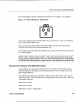
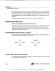
Set the Manifold Control Valves to Closed
Check the orientation of the Manifold Control Valves. The two valves on both sides of
the Quest Reactor Unit should be set to "Closed."
drain metered gas
solvent
G
closed vent
0
closed
utility
1
utility
2
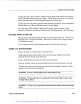
Connect Gas to the Quest Controller
The system gas to run the Quest is installed
via
a "Quick Connect" fitting on the right
rear of the Quest Controller Unit.
Artisan Technology Group - Quality Instrumentation ... Guaranteed | (888) 88-SOURCE | www.artisantg.com