artisan u TORO-3000 TORO-3200 with Ped 500 Adjustable Pedestal Motor Drive with Ped 500 Adjustable Pedestal Motor Drive TORO-3200 BT Bench Top Self Contained Transportable Heavy Duty Stitcher TORO-4000 R with Ped 500 Adjustable Pedestal Motor Drive TORO-4000 LA-25 with Ped-600 Adjustable Pedestal Motor Drive TORO-3000, TORO-3200 and TORO 4000 Series INSTRUCTION & SPARE PARTS MANUAL 2010.
Table of Contents I. Operating Instructions A. B. Caution Warnings Specifications Page 3. 3. 1. 2. 3. 4. 5. 6. 7. 8. 9. 10. 11. 12. 13. 14. 15. 16. CLEANING LUBRICATION. Where to oil the machine.
artisan u TORO-3000, TORO-3200 and TORO-4000 Extra Heavy Duty Cylinder Bed Lockstitch Compound Needle Feed Walking Foot Stitching Machines. CAUTION….. READ BEFORE OPERATING THIS MACHINE... 1. 2. 3. 4. 5. Lubricate the Stitcher before operating! Confirm you are plugging the electric motor into the correct rated voltage. Confirm the machine and motor are turning over in a counter-clockwise rotation.
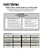
1. Normal stitching operation causes dust, lint, and dirt to build up around the moving parts of your TORO-3000, 3200 and 4000. Periodically clean around all the moving parts of the machine. Pay special attention to keeping the shuttle, shuttle race, and throat plate area clean. Simply wipe off the build-up with a clean cloth or blow off the dirt with compressed air. 2. TORO-4000 P Lubricate these five points through the front inspection cover.
3. SWITCH OFF THE MOTOR BEFORE REMOVING OR INSERTING A NEEDLE Artisan recommends that you use only “SCHMETZ” brand Needles. For Leather use size; 794 D, 794 S, 794 LR For Canvas, Nylon and Fabrics use size: 794 1. Turn the hand wheel counter-clockwise and raise the needle bar to its highest position. 2. Loosen the needle set screw #(1) remove the old needle and insert a new needle #2 into the needle bar. Push it up into the hole as far as it will go. 3.
. 1. Pull approximately 3 to 4 inches of thread off the bobbin and insert the new bobbin into the bobbin case so that when turning the bobbin turns counter-clockwise. 2. Pass the thread through the slot #(A) of the bobbin case and pull the thread until the thread passes under the bobbin thread tension adjusting spring and rests in the groove as pictured. 3. Leave at least 3to 5 inches of thread remaining and hanging out beyond the bobbin case. 4.
8. To Adjust the Stitch Length 1. Turn the adjuster nut #(1) counter-clockwise and push the handle in a downward direction for a longer stitch length. 1. For a shorter stitch length raise the handle and then turn the adjuster nut #(1) to lock in the handle. 2. A zero stitch length is in the middle of the slot. The longest stitch length is at the bottom of the slot located below #11 stamped on the face of the guide. 4. Pull the handle upwards to stitch in reverse.
11. 1. 2. 3. 4. The outside presser foot pressure is adjusted by loosening nut #(3). To increase the holding capacity of the Outside presser foot, turn the regulator # (1) clockwise. To reduce the holding pressure, turn the regulator Counter-clockwise. Be care not to fully unscrew the regulator. It is spring loaded and will “pop” out. Tighten the locking nut # (3). The standard height of the presser foot regulator # (1) from the casting to the top of the regulator screw is about 5/8” to 3/4”. 12.
Needle Needle Guard Shuttle Hook Point Shuttle Hook Race Carrier Frame Shuttle Hook Assembly with Bobbin Case Shuttle Hook Driver A. Complete Oscillating Shuttle Hook Assembly with Bobbin Case. B. Shuttle Hook Point. C. Bobbin Thread Tension Adjusting Screw. D. Bobbin Thread Tension Adjusting Locking Set Screw. E. Bobbin Thread Tension Spring. F. Bobbin Case. G. Bobbin Case Opener Latch. A. D. C. F. E. G. Photos Not To Scale. For Representation Purposes Only. Page 9 B.
Shuttle Hook Point B. Needle Guard Shuttle Hook Point to the Needle Relationship as viewed from behind the needle on the rear left side, and from left to right. Shuttle Hook Point B. Needle Needle Guard Shuttle Hook Race C. Shuttle Hook Point B. Shuttle Hook Point to the Needle Relationship as viewed from behind the needle and from the right to left side. Shuttle Hook Driver E. Bobbin Case Opener Latch G. SHUTTLE TO NEEDLE RELATIONSHIP: Correctly Timing the Needle with the motor switched off.
13. WALKING FOOT HEIGHT ADJUSTMENT To Adjust the height of the walking feet: 1. Loosen the nut #(6) and move the lever #(7) up to Decrease the walking foot height. (B) 2. Move the lever #(7) down in slotted bracket #(8) to Increase the walking foot height. (A) 3. Tighten the nut #(6) after completing the adjustment. 14. ADJUSTING THE NEEDLE-TO-SHUTTLE RELATIONSHIP B. C. E. Oscillating Shuttle Hook Driver Fig. 14-1 D. Shuttle Hook A. Thread Cast-off Area. Needle End Right Side Hand Wheel Fig.
Adjusting the Needle to Shuttle Position 1. Loosen the small Allen head screw #6. Then lightly snug the screw. 2. Loosen the two 6 mm Allen head screws #5. 3. With the stitch length lever set to the “0” position, turn the hand wheel in a counter-clockwise rotation and place the needle bar to the “Bottom-Dead-Center” position. At this point align Allen Screw #6 to the 9:00 O’clock position and in the same plane as the line “D” shown in Fig. 14-4. 4. Tighten the small Allen screw #6 5.
.
794 (D or S) NM 200, #25 Needle 15. The above adjustments are for stitching normal fabrics and do not apply to stitching heavy leathers for the TORO-3000 or 4000 R. Leather machines are specially adjusted for each application. The standard adjustments are only a starting point. 14.
16. 1. The thread breaks or tends to fray and then break. Skipped Stitches 1. A burr, cut, ruffness, or other imperfection was created on the needle plate, shuttle, shuttle race or presser foot by a broken or damaged needle. 2. Needle thread tension excessively tight. 3. Poor quality or incorrect thread size. 4. Machine is out of synchronization. 5. Excessive needle heat build-up. 1. 2. 3. 4. 5. 6. 7. 8. 3. Improper thread tension, irregular looking stitches, or excessive bobbin thread tension.
SUGGESTED REFERENCE GUIDE FOR artisan TORO 3000, 3200, 4000 R, 4000 P u LEATHER STITCHING MACHINES Recommended Schmetz brand Needle #794 1. Sewing on Thin Leathers of less than 8 oz. or up to1/8”: Use Schmetz brand Needles number 794 D or S, NM:160 Size 23, Canu 53:20MF1. “D” is a Triangle Leather Point and “S” is a Spear Point for leather. Under normal conditions the “D” points will last longer and the “S” point needles have a shorter life span but will make a straighter stitch.
Spare Parts List artisan u TORO-3000, TORO-3200 and TORO-4000 17.
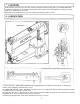
1. FRAME AND COVER COMPONENTS 18.
2. MAIN SHAFT COMPONENTS 19.
69 A. Page 20. 18.
.
4. PRESSER BAR COMPONENTS 22.
4. OUTSIDE PRESSER FOOT WITH TEETH FOR FABRICS A. B. C. D. E. F. G. H. 43423 43424 43425 43426 43405 43406 43424S 43425S Center Grover Leather Presser Foot Left Side Leather Presser Foot Right Side Leather Presser Foot Double Toe Leather Presser Foot Double Toe Presser Foot with Teeth for Fabric or Webbing (aka Blanket) Center Presser Foot with Teeth for Fabric or Webbing (aka Blanket) Short Toe, Left Side Leather Presser Foot Short Toe, Right Side Leather Presser Foot E D B C H G A page 23.
.
5. 25.
6. Hook Driving Shaft Components F. H. G. E. A B C D Shuttle Hook Parts A. GS 184 Locking Set Screw. B. GS 164 Thread Tension Adjusting Screw. C. GW 113 Thread Tension Spring. D. GW 114 Bobbin Push-out Spring. E. GN 115 Bobbin Case Body. F. GN 112 Shuttle Body. G. GW 112 Bobbin Case Opening Spring. H. GN 114 Bobbin Case Body Latch. I. GS 120 Bobbin Case Body Latch Screw. 26.
6. OSCILLATING SHUTTLE HOOK SPACER 27.
.
7. 29.
8. BOBBIN WINDER AND THREAD GUIDE COMPONENTS 30.
8. 31.
.
Winding the Bobbin on a TORO-4000 R 1. 2. 3. Raise the presser foot with the hand lifter lever. Insert the bobbin onto the bobbin winder spindle. Thread the winder in the order illustrated and wind the thread four or five turns onto the bobbin. 4. Push the bobbin winder trip latch (A) down. When the machine is operated the spindle will turn and start to wind the bobbin. 5. When the bobbin is fully wound, the trip latch will disengage and the spindle will stop.
.
artisan u TORO-3200 BT and TORO-4000 BT Servo Motor Adjustments NORMAL ON POSITION TO ADJUST VARIABLE HIGH SPEED LIMIT: . Letter “ d” is Illuminated . Push button “d” once. When n is illuminated, Press button “S”. #0 is lowest speed, #9 is fastest speed d= NORMAL Counter-Clockwise Rotation, d=Reverse, Clockwise Rotation . .
artisan A u TORO-3000, 3200 and 4000 THREADING Insert the thread through the upper wire thread guide (A), then around the top tension (auxiliary tension) in a clockwise rotation between the 2 disks, one revolution and back up to the same wire thread guide (A). D Bring the thread down and insert it into the main tension thread guide (B) artisan as shown.