
User Guide

Artison In-Ceiling Speakers QRG | 009-2068-01 1 of 1 45 Perseverance Way, Hyannis, MA 02601
Copyright 2021 Savant Systems, Inc. | 211104 www.savant.com/artisonspeakers | 508.683.2500
Artison In-Ceiling Speakers Quick Reference Guide
Box Contents
(1) ARCHT-x-xx (Artison In-Ceiling Speaker)
(1) Cardboard Template/Plastic Compass
(1) Magnetic Grille
Specifications
Environmental
Temperature 32° to 122° F (0° to 50° C)
Humidity 0% to 95% Relative Humidity (non-condensing)
Dimensions and Weights
Shipping
Dimensions
Height Width Depth
ARCHT-6 10 in 10 in 14 in
ARCHT-6-SSTT 7.25 in 10.5 in 10.25 in
ARCHT-8 12.25 in 12.25 in 14.25 in
ARCHT-8-SSTT 7.25 in 12.5 in 12.25 in
Diameter ARCHT-6: 8-7/16 in
ARCHT-8: 9-7/8 in
Weight Shipping:
ARCHT-6: 8.0 lb (3.63 kg)
ARCHT-6-SSTT: 4.0 lb (1.81 kg)
ARCHT-8: 13.0 lb (5.90 kg)
ARCHT-8-SSTT: 7.0 lb (3.18 kg)
Operating Parameters
Frequency
Response
ARCHT-6: 45 Hz - 20 kHz +/- 3 dB
ARCHT-8: 35 Hz - 20 kHz +/- 3 dB
Sensitivity ARCHT-6: 86 dB 1 W/1M
ARCHT-8: 91 dB 1 W/1M
Regulatory
RoHS Compliant
Preparation
– The speaker cable must be at least 16 gauge or larger and double
insulated for runs over 50 feet (15m).
– Ensure that the toggle clamps are rotated inward to their HOME
position prior to installation.
– The edge of the speaker holes must be at least 3/4” (19mm) away
from joists or studs whenever possible to allow clearance for the
toggle clamps.
– Use the cardboard template or the plastic compass provided with
your speaker to draw the speaker cut-out. The cut-out sizes and
in-wall depth measurements are detailed below:
Diameter Depth
ARCHT-6 7-1/4 in 3-9/16 in
ARCHT-6-SSTT 7-1/4 in 3-5/16 in
ARCHT-8 8-5/8 in 4 in
ARCHT-8-SSTT 8-5/8 in 3-7/8 in
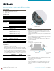
diffraction ring
removal notch
diffraction ring frameless grille
ARCHT-6
Installation
1. Using the proper tool, cut the appropriate sized hole in the ceiling.
2. Pull the end of the speaker cable through the speaker cut-out,
strip back a section of the jacket as needed, and then expose 1⁄2”
(13mm) of each conductor.
NOTE: To aid in speaker performance, a fibrous material, such as
fiberglass or polyester fiber, at this point can be placed behind the
speaker.
3. Connect the wire conductors to the terminals on the back of the
speaker by depressing each spring terminal, inserting the wire into
the hole, and releasing the terminal.
NOTE: Single-Point speakers have both the left and right channel
connections on the same speaker. Ensure that both channels are
connected and in phase.
4. Insert the speaker into the hole and orient the speaker towards the
listening area.
5. Turn each screw clockwise. The toggle clamps will rotate outward
to engage the ceiling material as shown.
Tighten 3
Phillips screw
Clean front
edge of cutout
to ensure a
flush fit.
NOTES:
– Grilles can be painted using multiple light coats of spray paint.
Grilles should be removed from the speaker and painted in a clean
environment to prevent contamination.
– Grilles are magnetically attached, and resistance will be felt when
removing them.
– The Mid Frequency (MF) switch is on the left and the High
Frequency (HF) switch is on the right, when looking at the foam
surface when the speaker is installed in the ceiling. Moving the
switches to the left decreases the level and to the right increases
the level.