Design Guide Campus Wireless Networks Validated Reference Design Version 3.
Copyright © 2008 Aruba Networks, Inc. All rights reserved. Trademarks AirWave®, Aruba Networks®, Bluescanner®, For Wireless That Works®, Mobile Edge Architecture®, People Move. Networks Must Follow., RFProtect®, The All Wireless Workplace Is Now Open For Business, and The Mobile Edge Company® are trademarks of Aruba Networks, Inc. All rights reserved. Legal Notice The use of Aruba Networks, Inc.
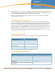
Contents Chapter 1 Chapter 2 Chapter 3 Chapter 4 Chapter 5 Introduction 5 Aruba Reference Architectures 5 Reference Documents 5 Contacting Aruba Networks 5 Aruba’s User-Centric Network Architecture 7 Understanding Centralized Wireless LAN Networks Introducing Aruba’s User-Centric Network 7 8 ArubaOS and Mobility Controller ArubaOS Mobility Controller 9 9 10 Multi-function Thin Access Points Access Point Air Monitor Mesh Portal or Mesh Point Aruba’s Secure Enterprise Mesh Network Remote A
AP Location and Density Considerations Office Deployment Voice Deployment Active RFID Tag Deployment Chapter 6 Mobility Controller Configuration 37 Required Licenses 37 Configuration Profiles and AP Groups Configuration Profiles Profile Types AP Groups Profile Planning 37 37 38 39 39 SSIDs, VLANs and Role Derivation SSIDs VLANs Role Derivation 39 40 40 41 Secure Authentication Methods Authenticating with 802.
Chapter 1 Introduction This design guide is one of a series of books that describes Aruba’s User-Centric Network Architecture and provides network administrators with guidelines to design and deploy a centralized enterprise-wide wireless LAN (WLAN) network for the most common customer scenarios. This guide complements the technical documentation you received with software and hardware releases for Aruba components.
Telephone Support 6 | Introduction Aruba Corporate +1 (408) 227-4500 FAX +1 (408) 227-4550 Support United States France United Kingdom Germany All Other Countries 800-WI-FI-LAN (800-943-4526) +33 (0) 1 70 72 55 59 +44 (0) 20 7127 5989 +49 (0) 69 38 09 77 22 8 +1 (408) 754-1200 Campus Wireless Networks Validated Reference Design Version 3.
Chapter 2 Aruba’s User-Centric Network Architecture This chapter provides an overview of a centralized wireless LAN architecture, followed by a high level technical overview of the Aruba User-Centric Network components and network design. This overview describes the technology, architecture, services, and applications that make up an Aruba User-Centric Network to help you make the right design choices, and select the appropriate solution components.
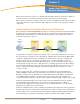
Introducing Aruba’s User-Centric Network In recent years, controller-based wireless switch architectures have been widely adopted to overcome the limitations of the autonomous AP. The Aruba centralized WLAN model shown below represents a structured model for WLAN deployment and ongoing management using a holistic approach to build enterprise WLANs that support user mobility without sacrificing security, manageability and scalability.
ArubaOS and Mobility Controller This section describes Aruba’s operating system features, optional add-on modules and the Mobility Controller that comprise Aruba’s User-Centric Network Architecture. ArubaOS The ArubaOS serves as the operating system and application engine for all Aruba Mobility Controllers, and is the core component that enables user-centric networks.
Mobility Controller The Aruba Mobility Controller is the center of the User-Centric Network. The Mobility Controller is a part of a purpose built, scalable appliance family that runs the ArubaOS operating system and software modules. It provides network administrators the ability to manage the system state and rapidly scope problems for individual users across a single Master/Local controller cluster in a network.
Multi-function Thin Access Points Aruba’s access points serve multiple functions depending on their role in the network. APs are either indoor or outdoor deployable; and are available with various options, such as fixed or removable antennas, single or dual radio APs, and depending on the AP, can operate in one or more of the a/b/g/n spectrums. Selection of hardware based options should be considered depending on the deployment.
Aruba recommends using dedicated Air Monitors for deployments of latency sensitive applications such as voice and video. Typically, one Air Monitor can provide security to the area served by up to four Access Points. Mesh Portal or Mesh Point In the Mesh Portal or Mesh Point role, the AP is taking part in Aruba’s secure enterprise mesh network.
Remote AP Using the Remote AP license, the AP can be used as a remote access device across a WAN. Plugging in to any Internet capable Ethernet port, the AP will create a secure tunnel using IPSec (AES) to a designated Mobility Controller. Typically this is done at corporate headquarters, or in regional data centers around the world for global deployments. The same SSIDs, authentication, and security are then available anywhere in the world.
the network grows to multiple clusters, a single centralized view across multiple Master/Local controllers of the following key operational data becomes highly desirable. z Users on wireless network z APs that users are connected to z 802.11 traffic statistics z AP failure notifications z Failover alternatives and backup coverage maps Mobility Management System Refer to Chapter 9, “Controller Clusters and the Mobility Management System™” on page 63 for more detailed information.
Chapter 3 A Proof-of-Concept Network To help set the stage for the complex campus network presented in Chapter 4 on page 19, it is useful to begin with a very small network. In this chapter, we consider a network that is typically deployed in a Proof-of-Concept (PoC) test involving a handful of Access Points and a Master Controller that provides guest and employee coverage to a conference room.
In this network, the AP has been deployed into a conference room, and is connected to the existing VLAN provided for wired users. In keeping with the concept of a network overlay, no reconfiguration or special VLANs need to be created as long as the access point has IP connectivity to the Mobility Controller. PoC Network - Logical and RF Design A common feature of centralized WLAN architectures is the ability to support many Service Set Identifiers (SSIDs) simultaneously from the same APs.
Users will associate to the Access Point and authenticate with the RADIUS server that already exists in the network. Employee users will use the Employee SSID, while guests will use the Guest SSID. Voice and data devices will associate to the Application SSID, and will be given a role based on the network services they are capable of accessing. Each user and device has a specific role and associated policy enforced by the stateful firewall in the Mobility Controller.
| A Proof-of-Concept Network Campus Wireless Networks Validated Reference Design Version 3.
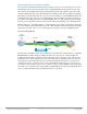
Chapter 4 Campus WLAN Validated Reference Design This chapter presents a more complex network model representing a common Aruba deployment in a large campus WLAN environment. Enterprise networks support thousands of employees, with rigorous service level expectations. To meet these requirements, a reference wired network architecture that defines Core, Distribution and Access elements has become well established among IT network professionals.
z Air Monitors – AMs are deployed at a ratio of one AM for every four APs deployed. These handle many of the IDS related duties for the network, and will assist in drawing accurate heat maps displaying graphical RF data. Aruba considers dedicated Air Monitors to be a security best practice because they provide full time surveillance of the air.
Aggregation Layer Mobility Controllers allow user traffic to stay close to associated servers; there is no need to tunnel user traffic all the way to the Management layer. z Wireless Access The Wireless Access layer is comprised of APs: single or dual-band, 802.11a/b/g or n, indoor or outdoor. They can be connected using wired switch ports, secure mesh or Remote AP.
| Campus WLAN Validated Reference Design Campus Wireless Networks Validated Reference Design Version 3.
Chapter 5 Mobility Controller and Access Point Deployment Deployment of the Mobility Controller must be considered based on a number of factors; the most important of which is identifying where user traffic is ultimately destined. The Validated Reference Design for Campus Wireless Networks depicts the Master Controllers residing in the data center and Local Controllers deployed at the distribution layer.
The Master is responsible for processing wireless intrusion detection system events, presenting the event and the corresponding wireless vulnerability and exploit (WVE) identifier. The Master is also responsible for handling location services correlation algorithms that compute the position of clients as well as rogue APs using signal strength measurements from APs in the network.
Master Controller Redundancy To achieve high availability of the Master Controller, use the Master Redundancy method. In this scenario, two controllers are used at the Management layer with one controller configured as an active Master and one configured as a standby Master. The two controllers will synchronize databases and RF planning diagrams, and will run a Virtual Router Redundancy Protocol (VRRP) instance between them accessed by a Virtual IP (VIP) address.
Configure Local Controllers to use the VIP address as their Master Controller address as follows. masterip 10.200.22.254 ipsec Local Controller Redundancy Local Controllers at the Aggregation layer also use VRRP instances for redundancy, but in a different model than the Master Controllers at the Management layer.
When one active Local Controller becomes unreachable, APs connected to the unreachable controller fail over to the standby Local Controller loading that controller to 100% capacity. Therefore each controller must have sufficient processing power and licenses to accommodate all of the APs served by the entire cluster. In this model, preemption should be enabled to force the APs to fail back to the original primary when it comes back online.
production AP load. By contrast Aruba supports up to 2,048 campus-connected APs and 8,192 Remote APs per controller which makes a 1:1 redundancy model feasible for the largest campus deployments. With a properly implemented distribution layer, this Active-Active Local Controller design with VRRP at the Aggregation layer features full redundancy while offering performance advantages by load balancing during normal operation.
In the second diagram the client device is placed into VLAN 200 by the controller following completion of the role derivation process. 200 Local Mobility Controller 200 arun_053b The user VLAN design will have implications for user connectivity and mobility across the network. To ensure that users do not overwhelm a single subnet, multiple VLANs can be configured to form a VLAN Pool in the Mobility Controller which users will be load balanced into dynamically.
VLAN Pools Network administrators prefer to keep subnet sizes down to what is commonly referred to as class C network. This is a network with a subnet mask of /24 (255.255.255.0), yielding 253 user devices per subnet. This size is considered manageable and will limit the broadcast domain size. In networks where this subdivision needs to be logical as opposed to physical VLANs are employed to limit broadcast domain size.
Aruba’s VLAN Pooling feature allows a set of VLANs to be assigned to a designated group of users. These VLANs can be configured as a non-contiguous set, a contiguous range, or a combination of the two. As an example, the set could be VLAN numbers 10, 20, and 30. It could also be VLAN numbers 2 through 5. These methods can be combined to provide a set such as 3, 5, and 7 through 10. This flexibility allows you to assign users to VLANs that may already exist in the enterprise.
With Mobile IP, the ArubaOS will automatically tunnel traffic between a roaming client’s original controller (the ‘Home Agent’) and the controller where the user currently terminates (‘Foreign Agent’). With Mobile IP and automatic tunneling, users are able to roam the enterprise without a change of IP address even when they are connected to controllers where their original subnet does not exist.
When the client roams off of its ‘home’ network to another network, the network is said to be attached to a ‘foreign’ network. The foreign network is defined as a network controlled by a different Mobility Controller than the one controlling the home network, but still within the same Mobility Domain. The IP address of the Mobility Controller on the foreign network becomes the client’s ‘care-of address’.
least two connections setting up redundant links to two data center distribution switches. With the Active-Standby configuration recommended in this VRD, this yields a full mesh between the two controllers and the distribution switches. The MMC-3600 does not have redundant power supplies; connect each appliance to discrete power sources in the data center.
VLAN at the Local Controller where a VLAN trunk already exists. This also allows for mobile IP functionality without client software as the intervening VLAN between the AP and the controller is never seen by the client. AP Power and Connectivity The AP can use DHCP for IP addressing and can automatically discover the Mobility Controller through a number of methods making it easily added to any existing employee port and VLAN.
Be sure to remember that RF travels in three dimensions. In a multi-floor building, the strongest signal may be above or below rather than side-to-side. In all 802.11 networks the client, rather than the AP, makes the decision when to roam from one AP to another. The RF designer can use this to advantage by staggering APs from floor-to-floor. This will help ensure that client roaming behavior is predictable, and can improve how ARM makes decisions about channel selection and power settings.
Chapter 6 Mobility Controller Configuration Once the hardware has been deployed there are several design decisions required to build out a working production network. This includes VLAN and IP network design, as well as the loop back IP address selection and spanning tree usage. Many of the decisions will logically follow from where the network architect chooses to place the AP and controller in relation to one another.
names. This allows the administrator to define a particular profile once and reuse it as needed which reduces errors and data entry. The ArubaOS Profile system is set up so that the configuration flow goes from high level to low level in a hierarchical manner. Unlike other hierarchical systems such as LDAP, the system does not provide arbitrary levels of depth or inheritance. The ability to copy a profile when creating a new profile allows for rudimentary inheritance when the new profile is created.
AP Groups An AP Group is a unique combination of Configuration Profiles. In general, all profiles are available to be assigned to an AP Group to create a complete configuration. This flexibility in configuration allows you to do arbitrary groupings of APs such as ‘All Lobby APs’ or ‘All APs in California’ with different configurations on each. Each AP Group must include a minimum number of profiles, in particular, a Virtual AP Profile.
SSIDs SSIDs appear as the name of the network displayed in the ‘Available Wireless Networks’ screen on a wireless client. While many APs in the same network will share the same SSID, each will have a unique BSSID. This feature is often used to let users know which SSID they should attempt to associate to, and to provide different levels of security to each of the SSIDs, such as WPA, WPA2, and Captive Portal.
Role Derivation Aruba uses the term ‘Role Derivation’ to describe the process of determining which role is to be assigned to a user. The system can take into account the user’s credentials, location, time of day, and authentication type when deciding which role to assign. This system can be as detailed or as general as the administrator prefers.
Authenticating with 802.1X 802.1X was developed to secure wired ports by placing the port in a ‘blocking’ state until authentication completed using Extensible Authentication Protocol (EAP). EAP is a framework and allows many different authentication types to take place within the EAP authentication system; Protected EAP (PEAP) is most commonly used in wireless. In this mode, a TLS tunnel is created and user credentials are passed to the authentication server within the tunnel.
Using RADIUS and a WPA2 protected connection as an example, authentication occurs using 802.1X. The Mobility Controller forwards the request to the RADIUS server who performs the actual authentication and sends a response to the Mobility Controller. Once authentication completes successfully, encryption keys are passed to the Mobility Controller from the RADIUS server, along with the user’s access policies.
Authenticating with Captive Portal For clients that do not support WPA, VPN, or other security software, Aruba supports a Web-based captive portal that provides secure browser-based authentication. Captive portal authentication is encrypted using SSL (Secure Sockets Layer), and can support both registered users with a login and password or guest users who supply only an email address.
Configuring Roles for Employee, Guest and Application Users The Aruba system is unique; it combines user-based security as a part of the WLAN model. When a user is authenticated, using one of the methods discussed in the previous section, a role is applied to the user that is enforced via the firewall and the defined policies for that user. Employee Role Users who are company employees can be granted a role based on their specific job function, or simply be given a universal ‘employee role’.
Guest Role Guest usage warrants special consideration for enterprise wireless networks. It is not enough for guest users to be separated from employee users through VLANs in the network. Guests must be limited not only in where they may go, but also limited by what network protocols and ports they may use to access resources.
Good guest policy as implemented by the stateful firewall should only allow the guest to access the local resources that are required for IP connectivity. These include DHCP and possibly DNS if an outside DNS server is not available. All other internal resources should be off limits for the guest. This is usually achieved by denying any internal address space to the guest user.
Create aliases: netdestination “Internal-Network” network 10.0.0.0 255.0.0.0 network 172.16.0.0 255.255.0.0 network 192.168.0.0 255.255.0.0 netdestination “Public-DNS” host 64.151.103.120 host 216.87.84.
Create the auth-guest role: user-role auth-guest session-acl cplogout position 1 session-acl guest-logon-access position 2 session-acl block-internal-access position 3 session-acl auth-guest-access position 4 session-acl drop-and-log position 5 Configure the guest VLAN: vlan 900 interface vlan 900 ip address 192.168.200.20 255.255.255.0 ip dhcp pool "guestpool" default-router 192.168.200.20 dns-server 64.151.103.120 lease 0 4 0 network 192.168.200.0 255.255.255.
With the appropriate levels of encryption and authentication used, for different users associated and authenticated to the same AP at the same time, the system is completely secured. The unique combination of these security mechanisms and Aruba’s Role-Based Access Control (RBAC) gives an Aruba User-Centric Network far more control and granularity of user traffic than simply demanding a particular type of authentication and encryption.
Role Variation by Authentication Method Role assignment has many options under the umbrella of role derivation. While the system can simply use the role returned from the authentication server, it can also assign a role based on a number of attributes. When a user logs in using WPA2 they receive an open employee role, but when logging in with the same credentials using a captive portal, a reduced role is put into effect.
Advanced Denial of Service (DoS) protection keeps enterprises safe against a variety of other wireless attacks, including association and de-authentication floods, ‘honeypots’ and AP or station impersonations. Based on location signatures and client classification, Aruba access points will drop illegal requests and generate alerts to notify administrators of the attack.
‘Rogue Classification’ means the process of detecting the presence of a Rogue AP and determining which type it represents. The rogue AP classification algorithms allow the system to accurately differentiate between threatening ‘rogue’ APs installed on the Local network and nearby ‘interfering’ APs. Once classified as rogue, these APs can be automatically disabled through both the wireless and wired networks.
| Mobility Controller Configuration Campus Wireless Networks Validated Reference Design Version 3.
Chapter 7 RF Planning and Operation Wireless networks break many of the old rules when it comes to designing a network; as a result, new tools are needed to help administrators quickly and effectively deploy and maintain a wireless network. The following sections describe the RF Plan and Adaptive Radio Management (ARM) tools that Aruba provides to help operate the WLAN effectively and efficiently. RF Plan Tool RF planning, in the days of autonomous Access Points, was a painful experience at best.
The RF Plan tool is available on the Mobility Controller, Mobility Management System™, and in a standalone version. All of these versions use the same file format, allowing an RF plan to be developed prior to deploying a controller, and then imported into the RF Live application for viewing. Aruba recommends as a best practice that each customer completes a post-installation site survey to verify that the delivered coverage matches what was predicted.
The ARM system handles setting all power and channel setting, including moving the APs to new channel and power settings automatically when appropriate. The network administrator spends no time managing the RF environment even in the case of RF jamming attacks or interference from legitimate wireless sources in the same frequency. The system automatically determines the best settings, and can automatically move away from interference laden channels without any intervention.
Aruba recommends that the above settings should be run for a minimum of one hour, and if possible overnight. Once the network has settled, the following configuration should be used for normal ARM operation. These are the default settings.
Chapter 8 Voice over Wi-Fi As more enterprises move from purely data-driven applications and incorporate Voice over IP (VoIP) and streaming video delivery, the demands for quality of service and assured application delivery rise commensurately. Multi-media applications can literally break a wireless LAN not designed for application awareness and automatic flow control.
call quality. Jitter buffers are used in VoIP networks to smooth out this effect, but they add delay and must be as small as possible. Aruba Mobility Controllers adjust network settings to minimize jitter and maximize voice quality. Traffic Prioritization Aruba Mobility Controllers use traffic prioritization as one method to address delay and jitter.
simultaneous voice calls handled by a single AP must be limited. This limit varies based on network conditions and handset manufacturer, and is typically provided in a manufacturer’s design guidelines. Call admission control (CAC) is included with the Voice Services Module license. CAC lets the Mobility Controller limit the number of voice calls on an AP, and proactively move voice clients to a less-utilized AP.
| Voice over Wi-Fi Campus Wireless Networks Validated Reference Design Version 3.
Chapter 9 Controller Clusters and the Mobility Management System™ The Aruba Mobility Management System™ (MMS) is designed to give network administrators the ability to manage the system state and rapidly scope problems for individual users across one or more Master/Local Mobility Controller clusters. As the network grows beyond a single Master/Local cluster the configuration and troubleshooting of the system grows in complexity.
Configuration is handled by the same Profile system discussed n Chapter 6 on page 37. With Mobility Controller clusters grouped on the MMS console, different Master/Local clusters can share the same configuration or have different configurations by cluster. Configuration checkpoints and recovery can be performed, as well as the ability to configure changes but apply them at another time.
The MMS solution will produce a number of standard reports to help with trending and capacity planning, and can be easily configured to do custom reporting. With the built-in hard drive, reports are available for as long as twelve months. The visualization features of MMS allow the network operations center to quickly view information about the system and its users.
The same heat maps and location tools available on the controller are also available on the MMS. The location API further extends this capability by allowing 3rd party applications to directly access the system to provide additional custom services. These include RFIDs tags and custom built location applications. The MMS system uses a Java Web Start user interface; no additional client side software is required.
Appendix A Licenses To extend the base capabilities of ArubaOS, a number of licensed software modules provide additional functionality, including: Voice Services Module Delivers standards-based voice over Wi-Fi plus voice control and management innovations enabled by Aruba's application-aware architecture. VSM supports large-scale voice deployments and provides a foundation for fixed mobile convergence (FMC). Policy Enforcement Firewall Enforces user-based network access and application priority policies.
| Licenses Campus Wireless Networks Validated Reference Design Version 3.
Appendix B WLAN Extension with Remote AP Remote Access Point (RAP) solutions involve configuring a standard thin access point to provide a customer-defined level of service to the user by tunneling securely back to the corporate network over a wide area network. The WAN may be either be a private network such as a frame relay or MPLS network, or a public network such as a residential or commercial broadband Internet service.
The AP itself should be configured to perform split tunneling. In this configuration the AP will perform decryption of wireless traffic and bridge traffic locally when it is bound for a non-corporate address, and re-encrypt the session using IPSec from the RAP to the corporate controller. The connection to the Internet is protected with the same stateful firewall available on the Mobility Controllers to protect the user from inbound traffic.
Appendix C Alternative Deployment Architectures This Campus Wireless LAN Reference Architecture represents a large scale, highly available WLAN deployment model in a single large campus environment. While this is the recommended deployment for this environment, there are other reference architectures that are considered best practices at different scales, and for different types of customers.
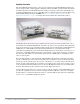
Figure 1 Mobility Controller located in the network data center Data center Internet arun_091 Figure 2 Mobility Controller located in the common wiring closet (IDF) Internet Data center PoE PoE arun_095 The controllers of choice in this deployment are dependent on AP count and PoE requirements. For small offices requiring PoE, the MC-800 or MC-2400 are both capable of providing power for APs.
Redundancy in this model is handled via Master redundancy, with both controllers acting as a Master Mobility Controller. One controller will be in standby, and should be deployed such that it is not serviced by the same power and data connections as the primary Master. Both Mobility controllers are typically deployed in the same data center. As with the Small Network Deployment, the Management and Aggregation layer are coresident in the same production controllers.
Figure 4 A single Master Mobility Controller pair backs up all Local Mobility Controllers Corporate data center Internet Private WAN Branch office Warehouse Retail store PoE arun_094 In this scenario the Local Controller a customer would select will typically be a MMC-3000 series controller. The Master Controllers should be MMC-6000 chassis systems to provide the greatest number of AP and users available on the backup system.
Pure Remote Access Deployment In some instances, the scale of the Remote AP solution or security requirements dictate that the internal Mobility Controllers serving campus users should not be used for termination of wide-area APs. Typically this means that dedicated Mobility Controllers are placed in the Demilitarized Zone (DMZ) of the network. These Mobility Controllers are solely responsible for terminating RAP and IPSec connections from users.