
Network Card User Manual


28 | Mobility Controller and Access Point Deployment Campus Wireless Networks Validated Reference Design Version 3.3 | Design Guide
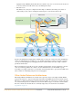
production AP load. By contrast Aruba supports up to 2,048 campus-connected APs and 8,192 Remote
APs per controller which makes a 1:1 redundancy model feasible for the largest campus deployments.
With a properly implemented distribution layer, this Active-Active Local Controller design with VRRP at
the Aggregation layer features full redundancy while offering performance advantages by load
balancing during normal operation. This form of redundancy is superior to an N+1 design with a
dedicated backup controller for the following three reasons.
z The network is already redundant – A properly implemented distribution layer has redundant links
between access layer switches and core routers. If any link other than the ones to the Aruba
Controllers fails, the system is already designed to route around that failure. Maintaining redundant
links or having the Mobility Controllers ‘straddle’ between distribution layer switches does not add
any additional reliability
z Loss of two controllers means a full network outage – Two Local controllers with physically isolated
data connections on separate, redundant power sources are already protected against a majority of
common failure modes. If both controllers lose power or link simultaneously it would most likely
affect many more network components resulting in a complete network outage no matter how many
redundant Local Controllers are available
z Better use of capital– In an N+1 design scenario at least one fully licensed Mobility Controller must
always be sitting idle awaiting a network failure. Using Aruba’s Active-Active capability allows both
Local Controllers to terminate APs and enforce policies and user roles within the network, while
providing hot backup for other members of the cluster
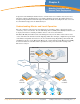
VLAN Design
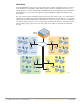
When performing VLAN planning it helps to remember that VLANs are used in two logically different
places on an Aruba Mobility Controller at the Aggregation layer. The first is the AP access side of the
controller, where APs will terminate their GRE tunnels. These VLANs carry encrypted traffic back and
forth between APs and the Controllers. The second is the user access side, where user VLANs will exist
and where traffic to and from the user will flow. During authentication, a process called ‘role derivation’
assigns the proper VLAN to each user and forwards traffic to the wired network if allowed.
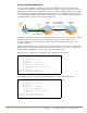
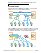
The user and access VLANs can also be visualized separately. In the first diagram below, the AP uses
VLAN 100 for access. This represents the physical connection of the AP to the network.
arun_053a
Local
Mobility
Controller
100
100
100