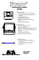
Observation System AOS58 AOC-75 Features - High resolution, 1/3” CCD Camera - Compact/Lightweight Aluminum Die Cast Body - Waterproof Housing - Waterproof Microphone - Waterproof Normal/Mirror Image Switch - Optional Wind deflector A B AOM-58 Features - 5” Monochrome Monitor - Dual camera Input - Brightness/Contrast/Day-Night Controls - Volume Control for Internal/External Speaker - Power/Stand By Button - Back-lit Front Panel Controls OCA-80 Features - 20 Meter Cable with Waterproof Connections - Oil,
AOS-58 IMPORTANT: The Voyager Observation system (AOS58) has been designed to provide years of trouble free operation. Please read this manual thoroughly. This manual contains instructions to ease the installation of the camera and monitor. The Voyager Observation system is a supplement to the standard rear view mirror systems, and will provide additional rear view vision when installed and maintained properly.
4 Use without Wind Deflector Screws (#8-32 UNC x 7.5) 4 Use with Wind Deflector Screws (#8-32 UNC x 9.0) AOM-58 Monochrome Monitor Qty. 1 5” Monitor 1 Snap-On Sun Visor 1 Monitor Bracket 1 Power Harness with locking connector 1 Range marker 4 Thumb screws (M5 x 15) with plain washer and spring washers 4 Attachment screws with washers (M5 x 12) OCA-80 Cable Qty. 1 20 meter cable with waterproof connector. Oil, gas, and grease resistant. UV stable Documents 1 Operators manual BEFORE INSTALLATION: 1.
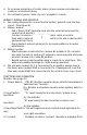
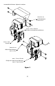
2. Attach camera to bracket using 8-32 UNC screws provided. Adjust angle as indicated in Figure 2. Use rear or end of bumper as reference point. 3. Wind deflector may be installed. This deflector is designed to reduce the build-up of dust, dirt and moisture on the camera lens. (See Figure 3). AOM-58 MONITOR 1. Attach monitor inside vehicle in a location convenient to the driver (e.g. center of dash, overhead, or in dash). 2. Use a compression plate to attach the monitor bracket to the dash or overhead.
4. To increase protection of cable, place all excess wire and extension cable in convoluted tubing. 5. Do not twist camera cable, do not cut pigtail, or cable. WIRING CAMERA AND MONITOR 1. See wiring diagram for connections to ignition, ground, and backup circuit. (See Figure 6) 2. Wiring camera: Drill a 19mm /3/4” diameter hole into the vehicle body near the camera and bracket. Connect camera connector to extension cable in vehicle.
“Day/Night” switch does not achieve the most desirable 5. Brightness: the picture. Variable control of brightness. Should be adjusted if “Day/Night” switch does not achieve the most desirable 6. Volume: speaker picture. Variable control of internal speaker and external volume. REAR OF MONITOR: See page 12. 1. Power Connection: PIN 1 not used PIN 2 Ground- Black wire PIN 3 Reverse circuit- Blue wire PIN 4 not used PIN 5 battery back-up- Yellow wire PIN 6 +12VDC ignition- Red wire 2.
3. Affix the “STOP” marker on the monitor screen over the image of the rear view bumper to locate the rear bumper. 4. The monitor screen is now “calibrated” for distances behind the vehicle of 3 feet, 6 feet and 9 feet.
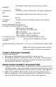
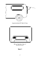
1.401 2.601 Camera Mounting Hole Pattern Figure 1 6 1.010 .534 5-0.165 Dia.
80° Approximately 80° Field of View Back of Vehicle, View at Monitor Screen Figure 2 7
Included Wind Deflector- Optional Installation Screw for use w/Wind deflector #8-32 x 3/8" 4mm x .7mm x 25.4mm Phillips Hex Head Screw w/Washers 4mm x .7mm Hex Nuts Screw for use Without Wind Deflector #8-32 x 5/16" 4mm x .7mm x 25.4mm Phillips Hex Head Screw w/Washers 4mm x .
Plain Washer Spring Washer Dashboard or Overhead Steel Plate Reinforcement (Recommended for Secure Mounting) Figure 4 9
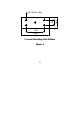
20° 20° 110.0° 5.275 6.240 Monitor Mounting Hole Pattern Figure 5 10 2.677 2.250 5-0.236 Dia.
Figure 6 11 TO MONITOR TO MONITOR CAMERA "A" INPUT 1A 3A REAR OF MONITOR 18 TEW YEL (Battery) (STRIPED AND TINNED) 18 TEW BLU (Reverse Trigger) (STRIPPED AND TINNED) 18 TEW BLK (Ground) (FEMALE BULLET DISCONNECT) 18 TEW RED (12V) (MALE BULLET DISCONNECT) GROMMET TO SEAL THROUGH VEHICLE INTERIOR 20 METERS WATERPROOF CAMERA CONNECTION EMI FERRITE CORE WIND DEFLECTOR- OPTIONAL INSTALLATION
MONITOR FRONT VIEW A 1 B 2 3 4 5 6 MONITOR REAR VIEW 4 3 2 1 Monitor Operating Controls and Connections 12
MICROPHONE MIRROR/ "NORMAL" SWITCH Camera Features 13
INDICATOR 3 FT. 6 FT. WIDTH OF VEHICLE 9 FT.
SPECIFICATIONS: AOS58 System, 1 Camera AOC75 Camera Rated Voltage Operating Voltage Current Consumption 12VDC, Negative Ground 11 to 30 VDC 1.5 Amperes Sensitivity Signal System Image sensor 0.1Lux NTSC 1/3” B/W CCD w/electronic auto-iris 270K picture elements 110° (H), 80° (V) 2.44” (W) x 1.50” (H) x 1.96” (D) 6.20cm (W) x 3.81cm (H) x 4.98cm (D) 0.8 lbs. 0.36 Kg. Viewing Angle (approx.
15
Optional Product List: Televisions AVT-988 9” Color Television with Remote (12V) AVT-1498 13” Color Television with Remote (12V) VCP and DVD Player’s For use with TV’s and LCD AVP-7000 Video Cassette Player (12V) AVP-7285 Video Cassette Player (12V) Single Disc DVD Player Headphones Headphones with Pivoting Earcups Headphones with Volume Control on Cord Studio Quality Headphones Miscellaneous Remote Controls Wallmount Family Radio Service with 4 Handsets Replacement Handsets 12V Corded Vacuum Rechargeable F
Or visit our website at www.asaelectronics.
________________________________________________________________________ ________________________________________________________________________ 17
AOS58 Manual Revision C Date: 3/2001