® AOM701 7” FLAT PANEL COLOR OBSERVATION MONITOR OWNER'S MANUAL A B – + AOM701 Features: – 7” High Performance Color LCD – Built-in Audio Speaker with Volume Control and 12V Trigger – 2 Camera (A/V) Input with A/B Select Control – Backlit Controls and Day/Night Picture Modes for Nighttime Use – Auto/Manual Power On – Sun Visor Included Visit us at http://www.asaelectronics.com Patent Pending UDIOVOX PECIALIZED PPLICATIONS, L.L.C.
Important! – Please Read This Manual Before Installing! Congratulations on your purchase of a Voyager AOM701 LCD Observation Monitor. With proper installation and use, your AOM701 is designed to provide you with years of trouble-free operation. This manual contains important information required to properly install and operate the unit. Please read this manual thoroughly before beginning.
PA C K I NG C ONT E NT S: 90 DAY/ 12 MONT H LIMIT E D WAR R ANT Y WA R R A NT Y CA R D QT Y . 1 L CD MONIT OR QT Y . 1 SUN SHIE L D QT Y . 1 4” X 2” V E L CR O QT Y . 1 #8 X ¾” SE L F DR IL L B L A CK SCR E WS (HA R DWA R E B A G) QT Y .4 5’ INT E R ME DIAT E HA R NE SS QT Y . 1 #10 X 5/16” PHP T HR E A D FOR MING B L A CK SCR E W (HA R DWA R E B A G) QT Y . 4 POWE R HA R NE SS QT Y . 1 1 • 1 • • • • 2 • 2 • • • • 3 • 3 • • • • 4 • 4 • • • • ST OP ST OP SPL IT GR OMME T 1” O.
CONTROLS AND OPERATION A 1 2 + – B 3 4 5 1. Power/Stand-By Button The Power / Stand-by Button has two possible operations modes. a. Manual mode - Turned on manual by the user by pressing the Power #1 button. b. Stand-by mode - Turned on by a stand by trigger wire generally connected to the vehicles 12V reverse backup lights. Manual Mode wiring - For manual mode operation, the AOM701 should be wired as follows: ACC (+12V) Red wire should be connected to the vehicles accessory feed.
A B 2. A/B Input Select Button This control toggles the active display image back and forth between AV1 and AV2 inputs. AV1 is the default source for the Blue Stamdby trigger wire. 3. Day/Night Mode Button This control toggles the unit between “Day” and “Night” LCD illumination modes. In the “Day” mode, the LCD backlight intensity is at maximum. In “Night” mode, the LCD backlight is dimmed to a preset level that is more suitable for low light operation. 4.
INSTALLATION INSTRUCTIONS BEFORE YOU BEGIN INSTALLATION: Before drilling, be sure that no cable or wiring is on the other side. Clamp all wires securely to reduce the possibility of them being damaged during installation and use. Keep all cables away from hot or moving parts, and electrically noisy components.
5. There are 2 options for connecting the LCD monitor to the connection cable. If the application is such that the monitor is in close proximity to the connection cable, the AOM701 monitor can be connected directly to the connection cable. If the connection cable is mounted further from the monitor, use the 5’ intermediate cable included with the AOM701 to connect the monitor to the connection cable. If more cable length is needed, additional 5’ lengths of the intermediate cable can be purchased.
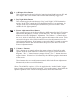
S – + (BLACK) CHASSIS GROUND (WHITE) AUDIO TRIGGER (RED) +12V SWITCHED (BLUE) +12V STANDBY TRIGGER TRIGGER (+12V) STANDBY GND S AOM701 LCD MONITOR TRIGGER (+12V) AUDIO 5’ INTERMEDIATE CABLE ACCESSORY ITEMS (optional cable lengths available, contact customer service for specifics) CONNECTION CABLE TYPICAL SYSTEM CONNECTION ACC (+12V) 8
REAR OBSERVATION INSTALLATION DISTANCE MARKER USE/INSTALLATION - PLACE INDICATOR MARKERS (CONE, BOX ANY REFERENCE OBJECT HANDY) BEHIND VEHICLE AS IN FIGURE A. - PLACE RANGE MARKER DECALS ON SCREEN OF MONITOR OVER IMAGE OF INDICATOR MARKERS ON GROUND BEHIND VEHICLE, AS VIEWED ON THE MONITOR SCREEN. - THIS GIVES YOU A VISUAL REFERENCE OF ACTUAL DISTANCE BEHIND VEHICLE, AS OBJECTS ARE VIEWED.
PANAVISE® MOUNT TEMPLATE (OPTIONAL ACCESSORY) 0.25 2.00 0.25 2.50 2.00 0.25 2.
TROUBLESHOOTING SYMPTOM CAUSE SOLUTION No power No +12V accessory, No ground, mis-wired/reversed Replace circuit fuse, monitor has protection device built-in/reset, check ground connection, verify power is being supplied Video/No audio Blue/white audio trigger wire not powered, Volume adjust down Blue standby wire not powered Connect to +12V ACC or reverse light circuit, turn volume adjustment up Low voltage, Brightness adjustment down Camera connection Check voltage power and ground connections,
PRODUCT SPECIFICATIONS LCD panel specifications: Size/Type 7” (diagonal) /TFT LCD Brightness 350 nit (min) 420 nit (typ.) Contrast Ratio 200 (min) 300 (typ.) View Angles (@ CR³10) Top (12 o’clock): 30°(min) Bottom (6 o’clock): 50°(min) Horizontal: ±50° (min) Response Time Rise: 12ms (typ.) ; 50ms (max) Fall: 18ms (typ.) ; 60ms (max) Back light Type Back light Life CCFL 30k hrs (min) ; 40k hrs (typ.