E6-B Flight Computer Instructions This instruction booklet can be used with the three different E6-B models available from ASA. If you have a different model than the one depicted, some parts of your computer may appear slightly different from the computers pictured in this booklet. However, the calculations are accomplished with the same method and produce the same answers. © 1992 – 2000 ASA Aviation Supplies & Academics, Inc. 7005 132nd Place SE Newcastle, WA 98059-3153 All rights reserved.
Contents Page Instructions for Using ASA Flight Computer ...... 4 The Slide Rule Side .......................................... 5 Time, Speed, and Distance Problems .............. 8 Fuel Consumption Problems ........................... 11 Conversions .................................................... 13 Nautical to Statute Miles ............................ 13 U.S. Gallons to Imperial Gallons ................ 15 Quantity/Weight Conversions .....................
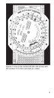
Instructions for Using ASA Flight Computer Your ASA E6-B Flight Computer has two main parts: a circular slide rule side for making quick calculations, and a wind side for computing ground speed and wind correction angle. The slide portion of the circular slide rule side also includes quickreference material.
The Slide Rule Side The term “circular slide rule” shouldn’t be intimidating. This side of your computer simply consists of a rotating disk with numbers on the middle scale, which when set against similar numbers on the fixed portion (outer scale), allows you to solve problems of time, speed, and distance, calculate fuel consumption, and make conversions between measurements such as statute and nautical miles. The inner scale on the rotating disk is graduated in hours.
Now look at the number 15 on the disk. Between 15 and 16 each calibration mark is equal to .2 and would be read as 15.2, 15.4, etc. If you were solving a problem with an airspeed of 150 knots, the first calibration past 15 (150 in this case) would be 152. The spacing changes again at the number 30, where each calibration becomes .5, and at 60, where each calibration equals 1. Before you read a value from the disks, be sure you understand what each line of calibration is equal to.
Figure 2. Line up the number 60 (the rate arrow) with the number 12 on the outer disk (or, scale).
Time, Speed, and Distance Problems The rate arrow on the disk is always set to indicate a value per hour on the outer scale. There are three basic time-speed-distance problems. In two of these problems you know the rate, while in the third problem, the rate is part of the answer you are looking for. To find the Time En Route, let’s assume you know your airspeed is 150 knots (nautical miles per hour). 1. Set the rate arrow to 150. See Figure 3. 2.
Figure 3 Figure 4 9
In the final and most common type of time-speeddistance problem, the time and distance are known, and you need to solve for unknown speed. The rate arrow represents the answer. You will have flown between two known ground reference points 26 NM apart and checked the time between them to be: 13 (thirteen minutes, that is, not thirteen hours). 1. Set thirteen minutes on the middle scale opposite to 26 on the outer scale. See Figure 5. 2. The rate arrow points to your ground speed, 120 knots.
Fuel Consumption Problems Problems involving fuel consumption, fuel endurance, and fuel capacity are solved using the same numbers you used in the time-speed-distance problems. With the exception of time values, only the names change. Assume that your airplane’s Approved Flight Manual indicates fuel consumption of 8.4 gallons per hour at a given power setting and that the usable fuel capacity is 64 gallons. How many hours endurance do you have in the tanks? 1.
When you paid for your fuel you noted on the delivery ticket that it took 32 gallons to top the tanks. You flew four hours and twenty minutes before stopping for fuel. What was the average fuel consumption? This time the rate arrow provides the answer. 1. Set 4:20 on the inner scale (or 260 on the middle scale) opposite of 32 on the outer scale. See Figure 7. 2. The rate arrow indicates the average fuel burn rate: 7.4 gallons per hour.
Conversions You can’t solve a problem unless the values agree. You can’t mix statute and nautical miles, gallons and liters, or Fahrenheit and Celsius. Your ASA E6-B Flight Computer makes it possible for you to convert between values with simple settings of the middle scale. Nautical to Statute Miles Distances on sectional and world aeronautical charts are in statute miles. Your airspeed indicator usually reads in knots, or nautical miles per hour.
You can convert either nautical or statute miles to kilometers. Find the KM marking on the outer scale. Set the known value beneath the NAUT or STAT arrow as before, and read kilometers under the KM marking. For example, to convert 115 statute miles to kilometers: 1. Set 115 opposite of the STAT arrow. 2. Read 185 under the KM marking. See Figure 9. Figure 9 Try these sample problems: (Answers are on Page 37) 1. 2. 3.
U.S. Gallons to Imperial Gallons Your Approved Flight Manual lists fuel capacity in U.S. gallons, but in many countries fuel is delivered in Imperial gallons. Arrows marked U.S. GAL and IMP. GAL are provided on both middle and outer scales to help you convert between these quantities. Your tanks are placarded to hold 64 U.S. gallons. How many Imperial gallons will they hold? 1. Line up the U.S. GAL arrow on the middle scale opposite the IMP. GAL arrow on the outer scale. 2. Find 64 on the middle scale. 3.
middle scale and read 38.5 U.S. gallons on the outer scale. Quantity/Weight Conversions Aviation gasoline weighs 6 pounds per U.S. gallon. For weight and balance calculations, aviation gasoline weight-per-gallon can be determined by lining the U.S. GAL arrow on the middle scale with the FUEL LBS arrow on the outer scale. Fuel gallons are read on the middle scale and fuel weight on the outer scale. To find the weight of 32 U.S. gallons: 1. Align the arrows. 2.
Figure 12 1. Align the arrows. 2. Read 15 pounds on the outer scale opposite of 2 gallons on the middle scale. See Figure 12. Imperial gallon weight of fuel and oil may also be determined in the same manner by lining up the IMP. GAL arrow on the middle scale with the FUEL LBS or OIL LBS arrow on the outer scale. You can convert liters to U.S. gallons, pounds to kilograms, or feet to meters by aligning the appropriate arrows on the middle and outer scales. For example, to convert pounds to kilograms: 1.
Using the Altitude and Speed Correction Windows Altimeters and airspeed indicators are designed to give correct indications under standard conditions at sea level. The consistency of the earth’s atmosphere does not change linearly as you gain altitude; its density is affected by variations in temperature and pressure. The E6-B provides windows on the slide rule side so you can allow for these variations when converting calibrated airspeed to true airspeed or indicated altitude to true altitude.
Figure 13 3. Read the density altitude over the arrow in the DENSITY ALTITUDE window. See Figure 13. Figure 13 shows a pressure altitude of 15,000 feet set opposite an outside air temperature of -15°C. A calibrated airspeed of 145 knots converts to a true airspeed of 183 knots and a density altitude of 15,000 feet under these conditions. Here are some sample problems: (Answers are on Page 37) 1. 2. 3.
Converting Mach Number to True Airspeed To convert Mach Number to True Airspeed (or vice versa), rotate the inner dial until you see the Mach No. Index inside the airspeed correction window on the inner dial. Line up the true or outside air temperature (do not use Indicated Air Temperature) opposite this Mach No. Index. Mach Number on the inner scale reads opposite True Airspeed (in nautical miles per hour) on the outer scale.
True Altitude When the air is colder than standard your altimeter can mislead you into thinking you are higher than you actually are. Determine true altitude by the following steps: 1. Determine pressure altitude by setting 29.92 momentarily on the altimeter. 2. Set pressure altitude next to outside air temperature in the altitude correction window. 3. Subtract station altitude from indicated/calibrated altitude to determine calibrated altitude AGL. 4.
If the station altitude is unknown, read calibrated altitude MSL on the middle scale and true altitude MSL on the outer scale. In Figure 15 the pressure altitude is 10,000 feet, station altitude is 5,000 feet, outside air temperature is -19°C, and your indicated (calibrated) altitude is 12,000 feet. The difference between 5,000 feet station altitude and 12,000 feet indicated altitude is 7,000 feet.
ground speed will indicate 450 feet per minute, while a jet following that same gradient at 240 knots ground speed will show a vertical speed of 1,200 feet per minute. You can convert feet per mile to feet per minute by placing the rate arrow opposite to the ground speed, finding the feet per minute value on the outer scale lined up with the feet per mile value on the middle scale. Try these two examples: 1. Set the rate arrow opposite of 90. 2. Find 300 feet per mile on the middle scale (see Figure 16). 3.
(Answers are on Page 38) GROUND SPEED 1. 2. 3. FEET PER MILE REQUIRED 120 100 150 FEET PER MINUTE 350 250 300 Off-Course Problems When you navigate by pilotage, you will occasionally find your airplane has drifted off the planned course due to the wind.
Figure 17 opposite of the distance off course; read additional degrees of heading change opposite of the rate arrow. Add the two answers and apply the result to your heading. Example: Your destination is 235 miles ahead (see Figure 18 on the next page). 1. Set 235 on the middle scale opposite 8 on the outer scale. 2. Read 2.4° at the rate arrow. 3. Change course 6° (3.8 + 2.4) toward the course line and, if the wind doesn’t change, you will rejoin the original course line as you approach the destination.
Figure 18 Figure 19 shows the setups in equations.
The Crosswind Table To determine headwind, tailwind or crosswind component quickly and easily, you must know the angle between your course and the reported wind direction. You also must know the reported wind velocity. This will be especially helpful in anticipating the effect of wind when landing, because wind reported by a tower, flight service station, or ATIS is surface wind.
Example: The ATIS reports the wind as from 230° at 14 knots with runway 18 in use. In the column headed by 50° (see Figure 20) there is a box for 10 knots and a box for 20 knots. Interpolating, the headwind component will be 9.5 knots and the crosswind component will be 11.5 knots. Those are “approximate” because the wind when you touch down will rarely be exactly what was reported. The Wind Side of the Slide Directions for use of the wind side are printed on the slide (see Figure 21).
–E TC +W VAR = MC –L MC+R WCA = MH MH ± DEV = CH Figure 21 Note: Some slight variations exist on the E6-B models, but the calculations are the same; be sure to count the lines accurately.
that represents the true airspeed. Read ground speed under the grommet. The wind correction angle is measured right or left of the center line. Be sure to count the degrees accurately — the value of each line changes at the 100, 150, or 250 knot arc, depending on the E6-B model you are using (see Note below Figure 21). Example: You have laid out a course on a sectional chart and measured it to be 090° true using your plotter.
Figure 22 Here are some sample problems: (Answers are on Page 38) TRUE WIND WIND TRUE DIREC. VELOCITY COURSE TAS 1. 2. 3. 4.
Figure 23 Determining Winds in Flight Winds aloft forecasts are frequently in error. If you have an autopilot and some free time, you can calculate the actual winds at your location and altitude. It helps if you have GPS, too. To solve an inflight wind problem you need your ground speed, true heading, true course, and true airspeed.
check came out to be 120 knots, and you calculate the true airspeed at your altitude to be 140 knots. 1. Set 180° at the TRUE INDEX on the wind side of the computer. 2. Move the slide until the grommet falls over the line marked 120. The true heading is 20° less than the true course, which means that you have a 20° left wind correction angle. 3.
Figure 24 34
Figure 25 35
Notes 36
Answers to Sample Problems Time-Speed-Distance Problems, Page 10 1. 4 Hours and 12 Minutes 2. 138 Knots 3. 183 Nautical Miles 4. 110 Knots 5. 133 Nautical Miles Fuel Consumption Problems, Page 12 1. 26 Gallons 2. 12.8 GPH 3. 4 Hours and 28 Minutes 4. 25 Gallons 5. 1 Hour and 50 Minutes Distance Conversion Problems, Page 14 1. 23 Statute Miles, 37 Kilometers 2. 41.7 Nautical Miles, 77.2 Kilometers 3. 59.4 Nautical Miles, 68.4 Statute Miles Airspeed Conversion Problems, Page 19 1. 204 Knots TAS, 16,000' DA 2.
Altitude Correction Problems, Page 22 1. 9,750' True Altitude 2. 10,350' True Altitude 3. 7,200' True Altitude Feet per Mile vs. Feet per Minute Problems, Page 24 1. 700 FPM 2. 415 FPM 3. 750 FPM Wind Problems, Page 31 TRUE HDG GROUND SPEED 1. 288 143 2. 133 149 3. 014 163 4. 258 240 Wind Problems, Page 33 WIND DIREC. WIND VELOCITY 1. 002 17 2.