AWM900S High Power AM/FM/CD Player Owner’s Manual Designed Specifically for the Van and RV lndustries
Thank you for your purchase of the AWM900S. It is designed to give you good value and many hours of listening enjoyment. Please read this manual carefully, as it should be able to answer many of your questions about the operation and features of this product.
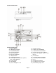
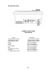
Controls Identification: Controls Identification 1) Display Window 2) CD Play/Pause Button 3) Band(AM/FM) Button 4) AUX Selector Button 5) Alarm Set Button 6) Alarm On/Off Buttons 7) CD Eject Button 8) Radio Tuning Control 9) Audio Adjust Selector Button (Volume, Bass, Treble, Balance) 10) Power Switch 11) Mute Button 12) Stereo Headphone Jack Page 3 13) 14) 15) 16) 17) Speaker Selector Volume Up Control Button Volume Down Control Button Time/Frequency Selector Button Preset EQ Button (Rock, Pop, Classi
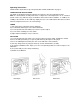
Operating Instructions: NOTE: Number in parenthesis (#) corresponds with “Control Identification” on page 3. LIQUID CRYSTAL DISPLAY PANEL The liquid crystal display (LCD) panel displays the frequency, time and activated functions. Note: It is characteristic of LCD panels that, if subjected to cold temperatures for an extended period of time, they will take longer to illuminate than under normal conditions. In addition, the visibility of the numbers on the LCD may slightly decrease.
AUXILIARY INPUT 1) Push Power Switch (10) “On”. 2) Using the source Selectors (4), choose the button labeled “AUX”. 3) If there is an external source (example: CD shuttle) connected to the Auxiliary Input Jacks (24) on the rear of the radio, then you can listen to your external source through the system. SETTING THE CLOCK 1) Push Power Switch (10) “On”. 2) Press the T/F button to display the clock 3) Hold the T/F button (16) and simultaneously use the H and M buttons (19 and 20) to adjust hours and minutes.
Wiring Color Code: WIRING COLOR CODE FOR AWM-900S COLOR ORANGE/WHITE STRIPE GREEN/WHITE STRIPE BLACK/WHITE STRIPE WHITE VIOLET BLUE LIGHT GREEN RED VIOLET/BLACK STRIPE YELLOW LT GREEN/BLACK STRIPE FUNCTION +12VDC IGNITION POWER +12VDC BATTERY POWER POWER GROUND (-12VDC) LEFT (A) SPEAKER (+) LEFT (A) SPEAKER (-) RIGHT (A) SPEAKER (+) RIGHT (A) SPEAKER (-) LEFT (B) SPEAKER (+) LEFT (B) SPEAKER (-) RIGHT (B) SPEAKER (+) RIGHT (B) SPEAKER (-) Page 6
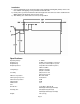
Installation: 1) Cut a mounting hole in the desired location using mounting hole diagram (below) and use the four 3x20min self tapping screws provided to mount the unit. 2) Route power, speaker and antenna cables through hole and connect to unit as outlined in the Wiring Color Code diagram on the previous page. 3) After making sure connections are correct, test operation.
WARRANTY 90 DAY / 12 MONTH LIMITED WARRANTY AUDIOVOX SPECIALIZED APPLICATIONS, LLC (the Company) warrants to the original retail purchaser of this product that should this product or any part thereof, under normal use and conditions, be proven defective in material or workmanship within 90 days from the date of original purchase, such defect(s) will be repaired or replaced (at the Company’s option) without charge for parts and repair labor.