AsantéHub 2072 Network Management Module Installation Guide
AsantéHub 2072 Network Management Module Installation Guide • Introducing the Network Management Module on page 4 • Installation on page 6 • The Front Panel on page 8 • Cable Connections to Other Devices on page 12 • Using AsantéTerm on page 19 • Using Telnet on page 21 • Using the Asanté Remote Management System on page 24 • Configuration Menu on page 31 • Segment Control on page 38 • Technical Specifications on page 41
AsantéHub 2072 Network Management Module Installation Guide Asking for Assistance Asanté Technical Support To contact Asanté Technical Support: Telephone (800) 622-7464 (408) 435-0706 Fax (408) 432-6018 Fax-Back1 (800) 741-8607 (408) 954-8607 Bulletin Board Service (BBS) (408) 432-1416 ARA BBS (guest log-in)2 (408) 894-0765 AppleLink mail3/BBS2 ASANTE.TECH FTP Archive2 ftp.asante.com Internet mail3 support@asante.com 1. 2. 3.
Tell Us What You Think Tell Us What You Think There’s always room for improvement and Asanté Technologies is interested in your comments and suggestions about our product user manuals. If you take the time to make suggestions, we will take the time to read and consider your suggestions for new manual releases.
AsantéHub 2072 Network Management Module Installation Guide Introducing the Network Management Module The Asanté 2072 Network Management Module (NMM) provides overall network management for the AsantéHub 2072 or NetStacker hub. By plugging the module into any one of the expansion slots in the chassis, the NMM works with the AsantéView network management software to monitor and control AH2072 NMM or NetStacker modules, gather statistics, monitor network traffic, and set alarm thresholds.
Introducing the Network Management Module With the NMM’s Segment Control buttons, you can manually isolate any AH2072 NMM or NetStacker module, or assign it to either of the chassis’ two segments.This can also be accomplished remotely using AsantéView In-Band and Out-of-Band software. Segment Control allows you to monitor and control both segments of the AsantéHub 2072 and its repeater modules.
AsantéHub 2072 Network Management Module Installation Guide Installation The NMM installation consists of: ❏ ❏ ❏ ❏ Grounding Requirements Checking Package Contents Grounding yourself Checking package contents Installing the module and checking its LEDs Connecting the module to other devices Before unpacking or handling the module, you must attach the grounding strap (provided in the package) to your wrist to discharge static electricity from your body or clothes.
Installation 2 Align the module with the inside edges of the card guides on any available slot in the chassis. Gently slide the module in until you can begin tightening the screws. See Figure 2.
AsantéHub 2072 Network Management Module Installation Guide The Front Panel The NMM front panel has several LEDs, ports, connectors, and switches, all used to monitor and maintain network activity and to enable network management capabilities. Figure 3 shows the parts of the NMM front panel.
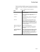
The Front Panel Table 2 identifies the NMM front panel components and explains the function of each. It also lists LED interpretations where appropriate. Table 2 Function of NMM Front Panel Components Name Function Ethernet MAC Address The physical address of this module and hub; preset at the factory. Reset button Resets the NMM only (interrupts traffic). When the module resets, power on diagnostics run automatically.
AsantéHub 2072 Network Management Module Installation Guide Name Page 10 Function Hub Status LEDs (bottom row of 8 LEDs per segment) Provides warning and packet collision data about the segment (not the module); the first four are warning LEDs, the second four provide the total percentage of packet collisions occurring at any instant on Segment 1 or Segment 2. LC - Late Collision. A collision which occurs after the 64 byte Collision window MC - Misaligned/CRC.
The Front Panel Name Function Segment 2 LED Lights to indicate that the module is currently on Segment 2 of the backplane. If both Segment LEDs are off, the module is not connected to either of the two segments. RS232 Connector (9-pin serial interface) Provides three types of connections: terminal connection, Out-of-Band direct connection with AMS using AsantéView, or Out-of-Band connection with AMS using AsantéView via a modem.
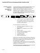
AsantéHub 2072 Network Management Module Installation Guide Cable Connections to Other Devices The NMM’s front panel has two connections (out-of-band) that provide attachment to other hardware devices such as PCs, Macs, or dial-up modems: ❏ ❏ AMS Link AsantéView Management System (AMS) Link RS232 connector The AMS Link specifically provides the following types of device connections: ❏ ❏ PC and Macintosh connections for Out-of-Band network management Hub interconnections for out-of-band (daisychained f
Cable Connections to Other Devices ∆ If you are managing only one hub, set DIP Switch 1 DOWN (END). 5 6 Set DIP Switch 2 DOWN (SETUP) on all hubs. 7 To connect an AsantéView Management Station to a hub, follow the instructions in "Connecting a Management Station to the Hub" on page 13. For a summary of DIP switch settings, see Figure 6 on page 15 and Figure 7 on page 16. If you change a DIP switch setting, you must reset the hub or NMM. Press the Reset button.
AsantéHub 2072 Network Management Module Installation Guide Maximum cable length between the AMS and the hub is 100 meters. NMM RS-232 1 2 RS-232 RJ-45 (AMS LINK) RJ-45 Mac AMS Link Extender DIN-8 or Mac RJ-45 PC AMS Link Extender DB-9 PC Figure 5 Summary of DIP Switch Settings Page 14 Using an AMS Link port to connect to a Management Station (Macintosh or PC) 2 Set DIP switches on the hub as shown in Figure 4 on page 13. 3 Reset the hub.
Cable Connections to Other Devices In the first Out-of-Band configuration, the AsantéView Management Station (AMS) is connected to a hub using one of the hub’s AMS Link ports and an AMS Link Extender. In the second, the AMS is directly connected to a hub using the hub’s RS232 connector and a straight-through RS232 cable.The third configuration shows a remote AMS connected to a hub over telephone lines using the hub’s RS232 connector and a modem.
AsantéHub 2072 Network Management Module Installation Guide The fourth configuration connects a terminal to an individual hub using the RS232 connector as a local management port.The fifth configuration connects an AMS to a single hub using one of the hub’s AMS Link ports and an AMS Link Extender.
Cable Connections to Other Devices To connect the hub to a modem, do the following: 1 2 3 Using the Local Management Port Connect the modem only to the end hub. Set DIP Switch 2 UP for this hub.You will not be able to manage this hub using AsantéView Out-of-Band via the AMS Link while this switch is in the UP position. Set up the modem for auto-answer. You can use the RS232 connector on the NMM as a local management port.This section describes the steps involved.
AsantéHub 2072 Network Management Module Installation Guide 1 Connect a straight-through RS232 cable to the RS232 connector on the NMM. Figure 9 shows a Macintosh RS232 cable being connected to the NMM RS232 connector.
Using AsantéTerm Using AsantéTerm Installing AsantéTerm AsantéTerm, provided with AsantéView In-Band and Out-of-Band, can be used to interrogate and program an Asanté hub using the Macintosh as a terminal. Follow this procedure to install AsantéTerm. 1 Insert the AsantéView disk into the floppy drive and double-click the disk icon to open it. 2 Copy the AsantéTerm program to your hard drive.The icon looks like the one shown in Figure 11.
AsantéHub 2072 Network Management Module Installation Guide Figure 12 Page 20 Asanté Remote Management System Main Menu using AsantéTerm
Using Telnet Using Telnet You can use Telnet to interrogate and program an AH2072 NMM NMM with a NetStacker hub or AsantéHub 2072.You can do this using any Telnet-capable computer, either directly connected to the hub or over the network. ∆ Information on installing Telnet is not provided in this manual. Refer to the documentation that comes with the Telnet software.
AsantéHub 2072 Network Management Module Installation Guide Copy the files to the AMS Images folder on the Macintosh. On the PC, copy the files to the same directory as the AMS executable (In-Band or Out-of-Band). Upgrading the Hub Image Code You can download the image code to the hub using either AsantéView In-Band or Out-of-Band.You do this by selecting the Software Upgrade command in the Configuration menu. See the appropriate AsantéView User’s Guide for information on performing software upgrades.
Using Telnet Figure 14 4 Sample Telnet Session Dialog Click the OK button. Figure 15 shows the Asanté Remote Management System Main Menu that appears for configuring an AsantéHub 2072.
AsantéHub 2072 Network Management Module Installation Guide Using the Asanté Remote Management System This section contains: ❏ ❏ ∆ General Guidelines The icons, menus, and screens for accessing the Asanté Remote Management System may differ depending on what computer you’re using. Once you’re in the Asanté Remote Management System, the menus look the same.
Using the Asanté Remote Management System Asanté Remote Management System Menu Tutorial The following short tutorial navigates through some of the Asanté Remote Management System menus.The tutorial adds the text “2072” to a hub’s previously-defined name. All examples show Telnet running on a Macintosh. We start with a Telnet session established with an AsantéHub 2072.The Asanté Remote Management System Main menu appears, shown in Figure 16.
AsantéHub 2072 Network Management Module Installation Guide Figure 17 Example General Configuration Screen The example shows “Office Hub” as the current hub name. If the hub has not had a name assigned to it previously, the Hub Name field will be blank. Page 26 2 Press the space bar to continue.The Asanté Remote Management System Main menu appears again (see Figure 16 on page 25). 3 Type c from the Asanté Remote Management System Main menu.
Using the Asanté Remote Management System Figure 18 4 Enter Password Prompt Type the password Asante (the password is case-sensitive) and press return. The Configuration menu appears, shown in Figure 19.
AsantéHub 2072 Network Management Module Installation Guide 5 Type a from the Configuration menu.This takes you to the System Administration Information menu, shown in Figure 20. Figure 20 System Administration Information Menu Note that the current hub information—name, contact, and location—displays above the menu choices on this screen (some or all of these fields may be blank for your particular hub). We’ll change the example hub’s current name,“Office Hub”, to “Office Hub 2072.
Using the Asanté Remote Management System Figure 21 7 Enter Hub Name Prompt Type Office Hub 2072 (or a different name if you wish) and press return. Note in the above example that even though it looks like we could just add the text “2072” to the end of the hub name, we actually have to type the entire line. If we typed “2072” only, the hub would be renamed “2072” rather than “Office Hub 2072”. Telnet sends the new name to the hub and the screen refreshes to display the current information.
AsantéHub 2072 Network Management Module Installation Guide Figure 22 8 9 System Administration Information Menu Showing New Hub Name Press q to return to the Configuration menu. Press q again to return to the Asanté Remote Management System Main menu. You’ve just completed the tutorial for navigating menus in the Asanté Remote Management System. If you want to leave the Telnet application at this time, choose Quit from the File menu.
Configuration Menu Configuration Menu This section shows you how to access the Asanté Remote Management System Configuration menu and then describes the menu choices you can use to configure your hub. All examples show Telnet running on a Macintosh. We start with a Telnet session established with an AsantéHub 2072. Accessing the Configuration Menu Use the following procedure to get to the Configuration menu. 1 From the Asanté Remote Management System Main menu, press c for Configuration.
AsantéHub 2072 Network Management Module Installation Guide System Administration Information Use to enter and transmit text strings defining the hub name, contact, and location. Out-of-Band Parameters Use to enter and transmit the Out-of-Band baud rate, dial string to be used when the AMS dials out on a modem, and the Out-of-Band password. Baud rate changes also will be effective on the terminal.
Configuration Menu Group Parameters Use to assign to a segment or isolate, meaning assign to no segment, a group. (A group is defined as all of the ports on an AsantéHub 2072 or NetStacker hub module.) Pressing n (Select Next Group) repeatedly cycles through the group choices. Pressing s (Assign/Isolate Group Segment) repeatedly cycles through the segment choices—1, 2, or Isolated for the AsantéHub 2072; 1 or Isolated for the NetStacker hub.
AsantéHub 2072 Network Management Module Installation Guide Pressing a sets the node summary aging time, which is the amount of time the hub stores node summary data. Each time a new device uses a port, or the frame type changes, the hub stores an entry in the Node Summary log. If the hub does not receive data again from that node within the specified aging time, the node data is purged from the log.
Configuration Menu Reset System Use to send an immediate Reset command to the hub, causing a soft reset.Terminal communication is lost briefly, then automatically reestablished. If you’re using Telnet, the connection is closed. Exit Configuration Menu Use to leave the Configuration menu and go back to the Asanté Remote Management System Main menu. Changing the Password You’re prompted for a password when you choose the Configuration menu from the Asanté Remote Management System Main menu.
AsantéHub 2072 Network Management Module Installation Guide Figure 24 3 Type c for Console Password. The Command> line changes to prompt you for the new password, as shown in Figure 25. Figure 25 4 Page 36 Configuration Menu example Enter New Password Prompt Type the new password and press return.You’re prompted to type the new password again.
Configuration Menu 5 Type the new password a second time and press return.The new password is sent to the hub and you’re taken back to the Configuration menu.
AsantéHub 2072 Network Management Module Installation Guide Segment Control The AsantéHub 2072 and NetStacker hub provide two discrete network segment interconnections.That is, any AsantéHub 2072 or NetStacker module, including the AH2072 NMM, can be connected to Segment 1, Segment 2, or neither segment (isolated). Segment connection assignment for any module can be done through NMM front panel controls or with AsantéView software.
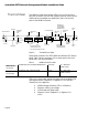
Segment Control Setting Segment Control Manually This section explains how to first select a module for a segment change and then perform the actual segment change. Figure 27 summarizes the steps. Change Segment button Select Slot button RS-232 % 0 AMS LINK 50 65+ OUT OF BAND 5 10+ SETUP ASANTEVIEW OUT-OF-BAND TERMINATION RS232/AMS LINK CONFIGURATION ISION % Step 1. Press Select Slot button until specified slot is chosen.
AsantéHub 2072 Network Management Module Installation Guide 3 Press the Change Segment button repeatedly until you have chosen the segment you want: Seg 1, Seg 2, or neither. 4 When you have chosen your segment, press both the Select Slot and Change Segment buttons together. In approximately two to three seconds, the change is made and the specified segment’s LED lights; the unspecified segment’s LED darkens. (See Figure 27 on page 39.
Technical Specifications Technical Specifications Physical Dimensions: 17” x 0.9” x 12” Weight: Approximately 2 lbs. (2.73 kg) Non-volatile Program Memory: Flash EEPROM and EEPROM Environmental Conditions: Operating Temperature: 0° to 40° C ambient Operating Humidity: 5 to 85% noncondensing Operating Altitude: 10,000 ft. (3,048 m) maximum Storage Temperature: -30° to 80° C Storage Humidity: 5 to 90% noncondensing Storage Altitude: 25,000 ft.
Index Index Symbols column 24 Numerics 2072h.cfg configuration file 21, 32 2072huxx.
Index password 34, 35 port parameters 34 segments 10, 39 defining hub IP address 32 dial string 32, 34 DIP Switches AMS PORT/SETUP 10 settings communicating with AsantéTerm 17 modem connected to hub 17 Out-of-Band daisychain 12 summary 14, 15 THROUGH/END 10 disabling port parameters 33 disabling termination 12 displaying current configuration 26 DRM Errors 33 E EEPROM local boot from 32 non-volatile program memory 41 resetting on NMM module 34 hubs, daisy-chaining and AMS Link connectors 12 examples 1
Index MIB AsantéHub 2072 5 support 4 pin assignments, RS-232 port 41 port connection default 34 enabling/disabling 33 Microsoft Windows and the NMM 4 MJLPs 33 modules, isolating 40 MSG LED 9 Multicast 33 Port Parameters menu item 33 port parameters, default values 34 prerequisites N R NCSA/BYU Telnet version 2.
Index segmenting the network, example 38 segments, LEDs while changing 40 Select Next Group menu item 33 Select Slot button 10, 38, 39 serial interface 11 session dialog 22 Session name field 23 setting hub name 29 SETUP LED 10 SFD Missing 33 Short Event 33 SNMP NMM support for 4 Port Link/Receive LED 9 Port Partition LED 9 SNMP Parameters menu item 32 SNMP protocols during remote boot 32 soft reset 35 Software Upgrade command 22 starting Telnet 22 subnet mask default 34 defining 32 summary, node 33 Syst