IntraCore™ 3500 Series Gigabit Ethernet Switches Getting Started Guide
Quick Start Guide Follow these steps to install your IntraCore switch: 1. 2. 3. 4. 5. Open the box and check the contents. See Chapter 1.1 Package Contents for a complete list of the items included with your IntraCore switch. Install the switch in an equipment or wall rack, or prepare it for desktop placement. Connect the power supply. Connect network devices to the switch. Refer to the User’s Manual on the accompanying CD-ROM for configuration and management capabilities.
Table of Contents Quick Start Guide 2 1. Introduction 1.1 Package Contents 1.2 LEDs 1.3 Front Panel Description 1.4 Management and Configuration 2. Installation and Setup 2.1 Safety Overview 2.2 Recommended Installation Tools 2.3 Power Requirements 2.4 Environmental Requirements 2.5 Cooling and Airflow 2.6 Installation Overview 2.7 Chassis Installation and Placement 2.8 Installing GBIC Interfaces 2.9 Installing Optional Hardware Modules 2.10 Connecting Power 2.11 Connecting to the Network 2.
Getting Started Guide
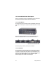
1 Introduction Thank you for purchasing the Asanté IntraCore 3500 Series Gigabit switch. The IntraCore 3500 series include 24- and 48-port 10/100 managed switches with a variety of hardware and software options. The IntraCore 3524 is a 24-port 10/100 managed switch with several optional hardware modules.
The system can operate as a stand-alone network or be used in combination with other IntraCore series switches in the backbone. 1.1 Package Contents The following items are included in your package: • • • • • • • • Switch AC power cord Rack mount brackets with screws Rubber feet Reference Guide User’s Manual (on CD-ROM) Getting Started Guide (this document) IntraCore 3500 CD-ROM Contact your dealer immediately if any of these items are missing. 1.
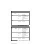
Port # LED Color Description N/A Power/ System Green Power is on Off Power is off Solid Green A valid 100 Mbps link has been established Solid Amber A valid 10Mbps has been established Off No link has been established Solid Green Full Duplex Solid Amber Half Duplex 1-24 (10/100) 1-24 (10/100) 10/100 Link Duplex Table 1-2 IC3524 Models-- Ports 1-24 Port # LED Color Description 25,26 Gigabit (speed) Solid Green A valid 1000Mbps link has been established Off No link has been es
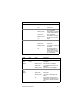
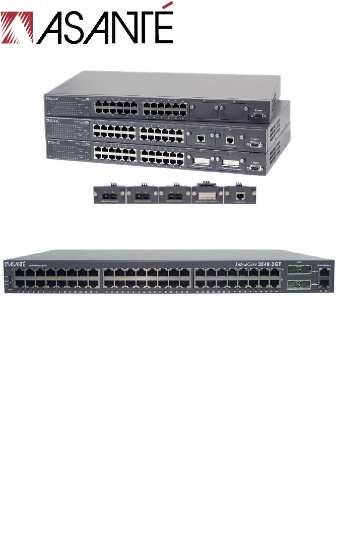
1.2.2 IC3548-2GT The IntraCore 3548-2GT switch has two LED status indicators for each of the 48 10/100 ports and the 2 Gigabit ports. Using the Mode button on the lower left of the front panel allows the user to convert between Link/Activity status and Duplex status displays. See the tables below for more information on the LED functions of the 3548.
Port # LED Color Description N/A Power/System Green Power is on Off Power is off 1-48 (10/100) Link/Activity Solid Green A valid 100Mbps link has been established Data transfer at 100Mbps A valid 10Mbps link has been established Data transfer at 10Mbps Blinking Green Solid Amber Blinking Amber 1-48 (10/100) Duplex Off No link has been established Solid Green Full duplex Solid Amber Half duplex Blinking Amber The switch is operating in half duplex No full-duplex link has been establis
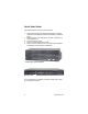
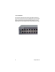
1.3 Front and Back Panel Descriptions Refer to the following sections for detailed descriptions of the front and back panels of the IntraCore 3500 series switches. 1.3.1 IC3524 Models From left to right, the front panel contains the following: Power and port LEDs; 24 10/100 ports; 2 optional module slots; and a console port. The switch is field upgradeable for use with 100BaseFX, 1000BaseSX, 1000BaseX GBIC or 10/100/1000BaseT modules.
From left to right, the back panel, shown below, contains: a console port; a 12V DC jack for an external power supply (IC35-RPS12, US part number 99-00777-01, sold separately); an AC socket (for primary power) and a power switch. 1.4 Management and Configuration There are three different methods by which a user can manage the switch: web, console/telnet, or with SNMP software.
nection to form a stack (multiple units sharing one IP address). The stacking feature is available on the IC3524 models, versions 1.1 or higher. See Chapter 2.11 Using the Stacking Feature for more details. 1.4.2 Web-Based Interface With Internet access, users can link directly to the local switch’s home page. Users can configure the switch, monitor the LED panel, and display statistics graphically. A detailed description can be found in Chapter 5. Web-Based Interface of the User’s Manual. 1.4.
2 Installation and Setup This chapter explains how to install and connect the switch to your network. To configure the switch for management, refer to the User’s Manual on the CD-ROM. The following guidelines will help you prepare to install the switch in such a way that it has the proper power supply and environment. 2.1 Safety Overview The following information provides safety guidelines to ensure your safety and to protect the switch from damage.
• • Do not tamper with the internal components of your switch. This could void your warranty Examine your work area for potential hazards (I.e. wet floors, ungrounded cables, etc.) and eliminate them before installing your switch For more safety information, please refer to the User’s Manual. 2.
Failure to observe these limits may cause damage to the switch and void the warranty. Avoid direct sunlight, heat sources, or areas with high levels of electromagnetic interference. 2.5 Cooling and Airflow The switch uses internal fans for air cooling. Do not restrict air flow by covering or obstructing air vents on the sides of the switch. 2.6 Installation Overview Follow these steps to install the switch: 1. 2. 3. 4. 5. Open the box and check the contents. See Chapter 1.
To mount the switch onto an equipment rack: 1. 2. 3. 4. 5. 6. Place the switch on a flat, stable surface. Locate a rack-mounting bracket (supplied) and place it over the mounting holes on one side of the unit. Use the screws (supplied) to secure the bracket (with a Phillips screwdriver). Repeat the two previous steps on the other side of the unit. Place the switch in the equipment rack. Secure the switch by securing its mounting brackets onto the equipment rack.
2. 3. Place the unit on a flat surface with a minimum area of 434.3 mm x 342.9 mm (17.1” x 13.5”) and support capacity of 10 kg (22 lbs ). Make sure there is enough ventilation space between the switch and surrounding walls or objects. 2.8 Installing GBIC Interfaces Instructions for installing, removing, and maintaining GBIC interfaces are provided in this section. 2.8.1 Installing a GBIC Note: GBICs are hot-swappable. This means that they can be inserted and removed while the unit is powered on. 1. 2.
2.8.3 GBIC Care and Handling Follow these GBIC maintenance guidelines: • • • • Unnecessary removal and insertion of a GBIC can lead to its premature failure. A GBIC connector has a lifetime of 100 to 500 removals/insertions GBICs are static-sensitive. To prevent ESD damage, follow your normal board and component handling procedures GBICs are dust-sensitive.
2.10 Connecting Power Use the following procedure to connect power to the switch: Important! Carefully review the power requirements (Chapter 2.3) before connecting power to the unit. 1. 2. Plug one end of the supplied power cord into the power connector on the back of the unit. Plug the other end into a grounded AC outlet. The Power LED will begin its initialization process. The front panel LEDs blink and the Power LED illuminates when it has initialized.
Note: There is no uplink port on this switch. All 10/100 ports on this switch are auto-sensing MDI/MDI-X. This advanced feature means that the 10/100 ports will automatically determine whether the device at the other end of the link is a hub, switch or workstation, and adjust its signals accordingly.
2.11.2 Gigabit Ethernet Ports Cabling Procedures Cabling requirements for the Gigabit Ethernet modules depend on the type of GBIC interface that has been installed. Use the following guidelines to determine the cabling requirements for your GBIC: • • • • 1000BaseSX GBIC: Cables with SC-type fiber connectors; 62.
• All stacked units are managed through connection to the master switch, via console, telnet or web interfaces Note: While the user may manage the stack via console, telnet or web interface, the initial formation of the stack may only be done by connection to a console. • The switches need no extra software, but they must all have the 1.1 firmware installed (see Chapter 3.14 in the User’s Manual for firmware upgrade instructions) Follow the steps below to install (build) a stack: 1. 2. 3.
console connection to the first unit. Type k in the Configuration Menu to access the Stacking Management menu, shown below. Type t to toggle the switch from “disabled” to “enabled”. Repeat for all remaining units.
4. 5. 6. 7. 24 After all units have had stacking enabled, connect the console to the first unit (the Master unit). Power cycle the whole stack, or, if the units are to be powered up separately, power the Master last. Go to the Master’s Stack Management menu and type s to begin the automatic formation of the stack. After the stack is formed, configuration and operation of the stack can begin (see the User’s Manual for information on configuring the switch(es) for operation.).
Appendix A Troubleshooting In the unlikely event your network does not operate properly, follow the troubleshooting tips below: 1. 2. 3. 4. CHECK YOUR POWER CONNECTION. Is the Power LED on? If not, plug the power cord into another known working AC outlet. CHECK YOUR NETWORK CABLES. Are the LINK LEDs on? If not, check the cable connections. Are the connectors seated correctly in each port? Make sure that the correct type of cable is connected to each port. CHECK YOUR GBIC CONNECTOR.
Getting Started Guide
Appendix B Safety and Regulatory Compliance FCC Compliance Statement This equipment has been tested and found to comply with the limits for a Class A digital device, pursuant to part 15 of the FCC Rules. These limits are designed to provide reasonable protection against harmful interference when the equipment is operated in a commercial environment.
Getting Started Guide
Appendix C Features and Specifications The IntraCore 3500 Series are Asanté’s most powerful, flexible workgroup switches. See the User’s Manual for detailed features and specifications. Features • • • • • • • Asanté Auto-Uplink™ on all 10/100 and 10/100/1000BaseT ports (auto MDI/MDI-X) 6.4 Gbps no-blocking bandwidth with wire speed forwarding (9.
Getting Started Guide
Appendix D Serial Port Pin Outs The console port is used to connect with a terminal using a DB-9 female connector. The setting is 9600-N81. See the table below for a list of pin outs.
Getting Started Guide
Appendix E Warranty and Support The IntraCore switch is covered by Asanté’s 3-year IntraCare™ product warranty and advanced technical support. An additional 2 year warranty is available through AsantéCare™. See the User’s Manual for more detailed information. If, after attempting the troubleshooting tips found here and in the User’s Manual, your switch is still not operating properly, contact Asanté Technologies, Inc. Technical Support (801-566-8991).
Getting Started Guide
Asanté IntraCore 3500 Series 35
IntraCore 3500 Series Gigabit Ethernet Switches Getting Started Guide Asanté Technologies, Inc. 821 Fox Lane San Jose, CA 95131 USA SALES 800-662-9686 Home/Office Solutions 800-303-9121 Enterprise Solutions 408-435-8388 TECHNICAL SUPPORT 801-566-8991 Worldwide 801-566-3787 FAX www.asante.com support@asante.com Copyright © 2002 Asanté Technologies, Inc. Asanté is a registered trademark of Asanté Technologies, Inc.