IntraCore® 35516 Series Layer 2/3/4 Gigabit Switches User’s Manual
IntraCore 35516 Series Layer 2/3/4 Gigabit Switches User’s Manual Asanté Technologies, Inc. 821 Fox Lane San Jose, CA 95131 USA SALES 800-662-9686 Home/Office Solutions 800-303-9121 Enterprise Solutions 408-435-8388 TECHNICAL SUPPORT 801-566-8991: Worldwide www.asante.com/support Copyright © 2003 Asanté Technologies, Inc. All rights reserved.
Table of Contents Chapter 1. Introduction 1.1 Features 1.2 Package Contents 1.3 LEDs 1.4 Front and Back Panel Descriptions 1.5 Management and Configuration 5 5 6 6 7 8 Chapter 2. Hardware Installation and Setup 2.1 Installation Overview 2.2 Installation into an Equipment Rack 2.3 Gigabit Interface Converters 2.4 Installing the Optional Emergency Power Supply 2.5 Connecting Power 2.6 Connecting to the Network 2.7 Setup 2.8 Setting Passwords 2.9 Configuring an IP Address 2.10 Restoring Factory Defaults 2.
Appendix D. Console Port Pin Outs 76 Appendix E.
Chapter 1. Introduction Thank you for purchasing the Asanté IntraCore 35516 Series Gigabit switch. The IC35516 is from a family of multi-media and multi-protocol switches capable of supporting Layer 2 switching and Layer 3 and Layer 4 protocols. They are designed to offer industry-leading performance at a very competitive cost of ownership. Important! This manual describes the hardware setup and configuration commands that are used by the IC35516.
1.2 Package Contents The following items are included in the switch’s package: • • • • • • Switch AC power cord Rack mount brackets with screws Rubber feet Setup Guide IntraCore 35516 CD-ROM Contact your dealer immediately if any of these items is missing. 1.3 LEDs The system’s front panel LED display allows the user to monitor the status of the switch. Refer to the following sections for LED information specific to the switch’s model. 1.3.
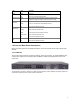
LED Color Description Power Green Power is on. Off Emergency Power Green Power is off, or main power supply has failed. Primary power has failed and optional power supply is powering the switch. Off BaseT10/100/1000 Green Link/Speed Yellow Optional power supply is in standby mode and primary power is working. A valid 1000 Mbps link has been established on the port. Off BaseT 10/100/1000 Green Duplex/Activity Blinking No link has been established on the port.
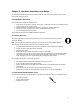
1.4.2 IC35516-G The front panel of the IC35516-G contains the following: power and port LEDs; 12 GBIC ports; 4 dualfunction Gigabit ports that support either 1000BaseT or GBIC-style Gigabit Ethernet ports; and a console port. The back panel, shown below, contains a 12 VDC jack for emergency power (optional), the primary power bay cover plate, the on/off switch, and the primary power outlet. 1.
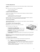
Chapter 2. Hardware Installation and Setup The following guidelines will help the user to easily install the switch, and to ensure that it has the proper power supply and environment. 2.1 Installation Overview Follow these steps to install the IntraCore switch: 1. 2. 3. 4. Open the box and check the contents. See Chapter 1.3 Package Contents for a complete list of the items included with the IntraCore switch. Install the switch in an equipment or wall rack, or prepare it for desktop placement.
2.1.3 Power Requirements The electrical outlet should be located near the switch and be easily accessible. It must also be properly grounded. Make sure the power source adheres to the following guidelines: • • Power: Auto Switching 90-260 VAC Frequency range: 50/60 Hz 2.1.
2.3 Gigabit Interface Converters The GBIC Interface is the industry standard for Gigabit Ethernet Interfaces. Some of the benefits of GBIC include reducing the components needed in a “spares” inventory, being able to choose from a wide variety of manufacturers with cross-vendor compatibility, and having competitive prices. Instructions for installing, removing, and maintaining GBIC modules are provided in following sections.
2.3.2 Removing a GBIC Caution: GBIC 1000T modules run hot under normal operating conditions. When it has been removed from the system, place it on a heat-resistant surface and allow the module to cool before handling. Note: Unnecessary removals/insertions of a GBIC module will lead to premature failure of the GBIC connector. The rated duty cycle for a GBIC module is 100 to 500 removals/insertions. Follow the steps below to remove a GBIC interface from a Gigabit Ethernet module: 1.
2.5 Connecting Power Important: Carefully review the power requirements (Chapter 2.1.3) before connecting power to the switch. Use the following procedure to connect power to the switch: 1. 2. 3. Plug one end of the supplied power cord into the power connector on the back of the switch. Plug the other end into a grounded AC outlet. Turn on the switch’s power. The power LED will begin its initialization process. The front panel LEDs blink and the power LED illuminates when it has initialized.
1000BaseT requires that all four pairs (8 wires) be connected correctly, using Category 5 or better Unshielded Twisted Pair (UTP) cable (to a distance of 100 meters). Table 2-2 shows the correct pairing of all eight wires. Pin Number 1 2 3 4 5 6 7 8 Pair Number & Wire Colors 2 White/Orange 2 Orange/White 3 White/ Green 1 Blue/White 1 White/Blue 3 Green/White 4 White/Brown 4 Brown/White Table 2-2 Pin Numbers and Wire Colors 2.6.
• • • Under the Settings tab, choose VT100 for Emulation mode Select Terminal keys for Function, Arrow, and Ctrl keys. Be sure the setting is for Terminal keys, NOT Windows keys Back under the Connect To tab, press the Configuration button • • • Set the data rate to 9600 Baud Set data format to 8 data bits, 1 stop bit and no parity Set flow control to NONE Now that terminal is set up correctly, power on the switch (boot sequence will display in terminal.
2.8 Setting Passwords The switch ships with a default of no enable password, which allows anyone on the network access to various privilege levels. To prevent unauthorized changes to the switch’s configuration, you should set an enable password for access to switch management. Follow the example below to assign a privileged password.
2.9 Configuring an IP Address The switch ships with the default IP address 192.168.0.1/24. Connect via the serial port in order to assign the switch an IP address on your network. The physical ports (or switchports) of the IC35516 are L2 ports, and cannot have an IP address assigned to them. By default, each switchport belongs to VLAN 1, a virtual interface (veth1) that may be assigned a primary, as well as any number of secondary, IP addresses.
2.10 Restoring Factory Defaults If you ever need to restore the switch to its factory default settings, follow the commands shown in the following screen. Router> enable Router# reload ? factory-default Reset ALL system parameters to factory default Router# reload factory-default The switch is now ready for configuration. Refer to the following chapters for management and configuration information. 2.11 System Boot Parameters The IC35516 has two boot banks to store its runtime code.
Chapter 3. Understanding the Command Line Interface (CLI) The switch utilizes Command Line Interface (CLI) to provide access to several different command modes. Each command mode provides a group of related commands. After logging into the system, the user is automatically in the user top (user EXEC) mode. From the user top mode you can enter into the privileged top (privileged EXEC) mode.
User top commands: Router> ? enable exit help ping quit show tracert cls Router> Turn on privileged mode command Exit current mode and down to previous mode Description of the interactive help system Send echo messages Exit current mode and down to previous mode Show running system information Trace route to destination Clear screen You may also enter a question mark after a letter or string of letters to view all the commands that start with that letter (with no space between the letter and the question
Router> enable Router# ? clear Reset functions clock Manage the system clock configure Enter configuration mode copy Copy from one file to another debug Debugging functions disable Turn off privileged mode command erase Erase a filesystem exit Exit current mode and down to previous mode help Description of the interactive help system no Negate a command or set its defaults ping Send echo messages quit Exit current mode and down to previous mode reload Halt and perform a cold restart show Show running system
Router# configure terminal Router(config)# ? access-list Add an access list entry arp Set static arp entry boot Modify system boot parameters duplicate-ip Duplicate IP Address detection Global Commands enable Modify enable password parameters end End current mode and change to enable mode exit Exit current mode and down to previous mode help Description of the interactive help system hostname Set system's network name interface Select an interface to configure ip Global IP configuration subcommands line Con
3.3.2 Router Configuration Mode Router configuration commands are used to configure an IP routing protocol and always follow a router command. To list the available router configuration keywords, enter the router command followed by a space and a question mark (?) at the global configuration prompt.
3.4 Advanced Features Supported within the Command Mode Entering a question mark (?) at the system prompt displays a list of commands available for each command mode. You can also get a list of any command's associated keywords and arguments with the contextsensitive help feature. To get help specific to a command mode, a command, a keyword, or an argument, perform one of the following commands: Command Purpose help Obtain a brief description of the help system in any command mode.
Example of Context Sensitive Help The following example illustrates how the context-sensitive help feature creates an access list from the configuration mode. Enter the letters “co” at the system prompt followed by a question mark (?). Do not leave a space between the last letter and the question mark (?). The system provides the commands that begin with co.
In the example above, a command has been issued that is unknown or ambiguous. Router(config)# router % Command incomplete. Router(config)# In the example above a command has been issued that is incomplete. In the following examples, various correct commands (using route) are displayed.
• • • • • • Editing Command Lines that Wrap Deleting Entries Scrolling Down a Line or a Screen Redisplaying the Current Command Line Transposing Mistyped Characters Controlling Capitalization 3.8.1 Moving Around on the Command Line Use the following commands to move the cursor around on the command line in order to make corrections or changes: Command Purpose Press Ctrl-B or press the left arrow key. Move the cursor back one character. Press Ctrl-F or press the right arrow key.
The command is not immediately executed, so that you may modify the command if necessary. If you enter a set of characters that could indicate more than one command, the system simply lists all possible commands. You may also enter a question mark (?) to obtain a list of commands that begin with that set of characters. Do not leave a space between the last letter entered and the question mark (?). For example, there are three commands in privileged mode that start with co.
Press Ctrl-U or Ctrl-X. Delete all characters from the cursor to the beginning of the command line. Press Ctrl-W. Delete the word to the left of the cursor. Press Esc D. Delete from the cursor to the end of the word. 3.8.5 Scrolling Down a Line or a Screen When using a command that list more information than will fill on the screen, the prompt --More-- is displayed at the bottom of the screen.
3.9 Passwords and Privileges Commands The following sections describe the password and privileges commands used to control access to different levels of the router: • • • enable password password service password-encryption 3.9.1 Enable Password To set a local password to control access to various privilege levels, use the enable password command in global configuration mode. Use the no form of this command to remove the password requirement.
3.9.3 Service Password-Encryption To encrypt passwords, use the service password-encryption command in global configuration mode. Use the no form of this command to restore the default.
Chapter 4. Managing the System and Configuration Files This chapter explains how to manage the system information, as well as how to manage the configuration files for the IC35516. 4.1 Managing the System This section discusses the following tasks needed to manage the system information of the IC35516: • • • • • • • Setting the System Clock Configuring the Host name Changing the Password Testing Connections with Ping Commands Tracing Packet Routes Enabling Syslog Displaying the Operating Configuration 4.
4.1.4 Trace Packet Routes To discover the routes that packets will actually take when traveling to their destinations, use the following command in top mode. Command tracert address Purposes Trace packet routes through the network. 4.1.5 Test Connections with Ping Tests The switch supports IP ping, which can be used to test connectivity to remote hosts, via their IP addresses. Ping sends an echo request packet to an address and “listens” for a reply.
4.2 Managing Configuration Files This section discusses how to download configuration files from remote servers, and store configuration files on the router at system startup. Configuration files contain the commands the router uses to customize the function of the IC35516. The setup command facility helps you create a basic configuration file. However, you can manually change the configuration by typing commands in a configuration mode.
4.2.2 Copying Configuration Files to a Network Server You can copy configuration files from the router to a file server using TFTP. You might wish to back up a current configuration file to a server before changing its contents, thereby allowing you to later restore the original configuration file from the server. Important! TFTP is not a secure protocol. Your server IP address and configuration file name will not be protected over the public Internet. Use TFTP only on a trusted LAN connection.
In order to restore a configuration file to an exact copy of a file stored on a server, you need to copy the configuration file directly to the startup configuration (using the copy tftp startup-config command) and reload the router.
Create or Modify Access Control for SNMP Community You can configure a community string, which acts like a password, to permit access to the agent on the router. Read Only (ro): The string that defines access rights for reading SNMP data objects. The default is public. Read-Write (rw): The string that defines access rights for writing SNMP data objects. The default is private. Important! Be sure to change the SNMP default community strings in order to prevent unauthorized access to management information.
but where there is only one path between any two points (the connections span the entire network, and the paths are branched, like a tree). All of the bridges (a switch is a complex bridge) on the network communicate with each other using special packets of data called Bridge Protocol Data Units (BPDUs).
Spanning Tree Port Configuration You can configure the following parameters from interface configuration mode: Router(config)# interface eth1 Router(config-if-eth1)# spanning-tree ? path-cost Set interface path cost port-priority Set interface priority Router(config-if-eth1)# Port Priority The port priority is a spanning tree parameter that ranks each port, so that if two or more ports have the same path cost, the STP selects the path with the highest priority (the lowest numerical value).
Chapter 5. Configuring IP The Internet Protocol (IP) is a packet-based protocol used to exchange data over computer networks. It is the foundation on which all other IP protocols are built. IP is a network-layer protocol that contains addressing and control information that allows data packets to be routed. This section describes how to configure the Internet Protocol (IP). Configuring IP Addressing A number of tasks are associated with configuring IP.
CIDR Prefix Class C Equivalent Host Addresses /27 1/8 Class C 32 Hosts /26 1/4 Class C 64 Hosts /25 1/2 Class C 128 Hosts /24 1 Class C 256 Hosts /23 2 Class C 512 Hosts /22 4 Class C 1,024 Hosts /21 8 Class C 2,048 Hosts /20 16 Class C 4,096 Hosts /19 32 Class C 8,192 Hosts /18 64 Class C 16,384 Hosts /17 128 Class C 32,768 Hosts /16 256 Class C OR 1 Class B 65,536 Hosts /13 2,048 Class C 524,288 Hosts An interface can have one primary IP address.
To assign multiple IP addresses to network interfaces, use the following command in interface configuration mode: Command ip address address I mask secondary Purpose Assign multiple IP addresses to network interfaces. 5.2 Establish Address Resolution A device in the IP can have both a local address (which uniquely identifies the device on its local segment or LAN) and a network address (which identifies the network to which the device belongs).
Interior gateway protocols are used to exchange routing information among routers in an autonomous network, such as a company’s LAN. A routing protocol determines how routers in a network share and update information and report changes, enabling a network to be dynamic instead of static. All IP interior gateway protocols must be specified with a list of associated networks before routing activities can begin on the switch.
5.4 Configuring RIP The Routing Information Protocol (RIP) is a commonly used interior gateway protocol (IGP) created for use in small, homogeneous networks. It is a distance-vector routing protocol, documented in RFC 1058. RIP uses broadcast User Datagram Protocol (UDP) data packets to exchange routing information. The IC35516 sends, or advertises, routing information updates every 30 seconds.
5.4.3 Specify a RIP Version By default, the software receives RIP Version 1 and Version 2 packets, but sends only Version 1 packets. You can configure the software to receive and send only Version 1 packets or only Version 2 packets. To do so, perform the following task in router configuration mode. Command version {1 | 2} Purpose Configure the software to receive and send only RIP Version 1 or only RIP Version 2 packets.
Router(config)# route-map map-tag permit 10 Router(config-route-map)# ? end End current mode and change to enable mode.
process. By specifying administrative distance values, you enable the router to intelligently discriminate between sources of routing information. The router will always pick the route whose routing protocol has the lowest administrative distance. There are no general guidelines for assigning administrative distances, because each network has its own requirements. The user must determine a reasonable matrix of administrative distances for the network as a whole.
Apply Offsets to Routing Metrics An offset list is the mechanism for increasing incoming and outgoing metrics to routes learned via RIP. You can limit the offset list with an access list. To increase the value of routing metrics, perform the following task in router configuration mode. Command offset-list access-list-name { in | out} Purpose Apply an offset to routing metrics. 5.4.
Important! Do not use plain text authentication in RIP packets for security purposes, because the unencrypted authentication key is sent in every RIP Version 2 packet. Use plain text authentication when security is not an issue (for example, to ensure that incorrectly configured hosts do not participate in routing). Command ip rip authentication mode {text | md5} Purpose Configure the interface to use MD5 digest authentication or let it default to simple password authentication.
IGMP The Internet Group Management Protocol (IGMP) manages the multicast groups on a LAN. IP hosts use IGMP to report their group membership to directly connected multicast routers. Routers executing a multicast routing protocol maintain forwarding tables to forward multicast datagrams. Routers use the IGMP to learn whether members of a group are present on their directly attached sub-nets. Hosts join multicast groups by sending IGMP report messages.
Changing the IGMP Version By default, the router uses IGMP Version 2, which allows such features as the IGMP query timeout and the maximum query response time. All systems on the subnet must support the same version. The router does not automatically detect Version 1 systems and switch to Version 1. Configure the router for Version 1 if your hosts do not support Version 2.
5.5.2 Configuring DVMRP This section presents the commands for configuring DVMRP IP Multicast Routing Protocol.
DVMRP must be enabled on the router for this command to be operational. Command probe-interval <5–30 seconds> Purpose Defines how often neighbor probe messages are sent to the ALL-DVMRP-ROUTERS IP multicast group address. Default value: 10 seconds Prune-age This value defines how long a prune state will remain in effect for a source-routed multicast tree. After the prune age period expires, flooding will resume. DVMRP must be enabled on the router for this command to be operational.
5.6 Using Access Lists An access list is a collection of criteria statements that the switch uses to determine whether to allow or block traffic based on IP addresses. Access lists can be configured to provide basic security on your network, and to prevent unnecessary traffic between network segments. When configuring an access list, you can add multiple statements by adding criteria to the same numbered list.
Router(config)# access-list A.B.C.D Source wildcard. Router(config)# access-list Router(config)# access-list Router(config)# exit Router# show access-list 1 deny 192.168.123.254 ? e.g. 0.0.0.255 1 deny 192.168.123.254 1 permit any {0.0.0.0 255.255.255.255} After entering the access list, use the show command from privileged mode, as shown above in the last line. Any lists you’ve created, as well as any remark entered for a list, will be displayed.
eq Operator - equal to gt Operator - greater then lt Operator - less then neq Operator - NOT equal to Router(config)# $ list 101 deny tcp 192.168.123.0 0.0.0.255 192.168.124.0 eq ? <0-65535> Protocol port number Router(config)# $ eny tcp 192.168.123.0 0.0.0.255 192.168.124.0 0.0.0.255 eq 21 Router(config)# $ eny tcp 192.168.123.0 0.0.0.255 192.168.124.0 0.0.0.255 eq 20 Router(config)# $ permit ip 192.168.123.0 0.0.0.255 0.0.0.0 255.255.255.255 Router(config)# exit Router# show access-list 5.6.
Router(config)# access-list 101 permit tcp 192.168.123.0 0.0.0.255 any eq 25 Router(config)# access-list 101 deny any Router(config)# interface eth1 Router(config-if-eth1)# ip ? access-group Apply an access-group entry Router(config-if-eth1)# ip access-group ? WORD access-list number or name Router(config-if-eth1)# ip access-group 101 ? in inbound direction out outbound direction Router(config-if-eth1)# ip access-group 101 out Router(config-if-eth1)# exit 5.
5.7.3 Configure Compatibility Compatibility configuration enables the router to be compatible with a variety of RFCs that deal with OSPF. Perform the following task to support many different features within the OSPF protocol. Command compatible rfc1583compatibility Purpose Enable the router to be compatible with the specifications in RFC 1583. 5.7.4 Configure OSPF Interface Parameters The user can alter certain interface-specific OSPF parameters as needed.
To configure the OSPF network type, use the following command in interface configuration mode. Command ip ospf network {broadcast | non-broadcast | point-to-multipoint | point-to-point} Purpose Configure the OSPF network type for a specified interface. 5.7.6 Configure OSPF for Non-broadcast Networks To configure routers that interconnect to non-broadcast networks, perform the following task in router configuration mode.
specific external routes as Type 7 LSAs into the NSSA. In addition, when translating Type 7 LSAs into Type 5 LSAs by NSSA ABR, summarization and filtering are supported during the translation. Use NSSA to simplify administration if you are an Internet Service Provider (ISP) or a network administrator that must connect a central site using OSPF to a remote site that is using a different routing protocol such as RIP.
5.7.11 Control Default Metrics OSPF calculates the OSPF metric for an interface according to the bandwidth of the interface. For example, a 64K link gets a metric of 1562, while a T1 link gets a metric of 64. If you have multiple links with high bandwidth, you might want to specify a larger number to differentiate the cost on those links. To do so, perform the following task in router configuration mode. Command auto-cost reference-bandwidth ref-bw Purpose Differentiate high bandwidth links. 5.7.
To force the autonomous system boundary router to generate a default route, perform the following task in router configuration mode. Command redistribute {kernel | connected | static | rip | bgp} [metric metric-value] [metrictype {1|2}][route-map map-tag] Purpose Redistribute routes into OSPF routing domain. 5.7.
To display various routing statistics, use the following commands in top mode. Command show ip ospf Purpose Display general information about the OSPF routing process. show ip ospf database show ip ospf database {asbr-summary | external | network | nssa-external | router | summary} show ip ospf database {asbr-summary | external | network | nssa-external | router | summary} link -state-id Display lists of information related to the OSPF database.
debug ospf event Display information on OSPF-related events, such as adjacencies, flooding information, designated router selection, and SPF calculation. debug ospf ism [events | status | timers] Display flooding information, SPF calculation on internal area-related events. debug ospf lsa [flooding | refresh] Display flooding information, SPF calculation on OSPF-generate related events. debug ospf nsm [events | status| timers] Display information on adjacencies.
The following commands are available under EXEC or Enable mode: Command show vrrp [brief | VRID] show vrrp interface IFNAME [brief] debug ip vrrp Purpose Displays a brief or detailed status of one or all VRRP VRID groups on the router. Displays the VRRP groups and their status on a specified interface. This command helps to debug VRRP operation. If this is enabled, then VRRP displays the debug messages onto the console. 5.
Use any of the following commands in top mode. Command show arp [interface] Purpose Display the entries in the ARP table. show access-lists [access-listname] show ip prefix-list [prefix-list-name] Display the contents of one or all current access lists. Display the contents of current IP prefix lists. show ip protocols Display active IP routing protocol statistics. show ip irdp Display IRDP values.
Chapter 6. VLAN Configuration Up to 4094 Virtual LANs (VLANs) are supported on the IC35516. The switch is shipped with a default VLAN with VLAN ID (VID) 1. All switchports (eth1-eth16) are included in the default VID 1. The default VID 1 cannot be deleted. 6.1 Creating or Modifying a VLAN Command Router(config)# vlan vid Purpose Enter a VLAN ID (2-4094), which will access config-vlan mode. Enter a new VLAN ID to create a VLAN, or enter an existing VLAN ID to modify a VLAN.
First, a VLAN is created and named tester. Router# configure terminal Router(config)# vlan 2 Router(config-vlan)# name tester Router(config-vlan)# exit Router(config)# exit Router# show vlan From the show vlan command, the new VLAN will be listed, but will not yet be active. Next, a switchport is chosen to belong to VLAN 2.
6.2 VLAN Port Membership Modes A switchport can be assigned to a VLAN by designating a membership mode. The membership mode determines the kind of traffic the port carries and the number of VLANs to which it can belong. The membership modes are as follows: • • • Static Access Trunk (IEEE 802.1Q) Dot1q Tunnel 6.2.1 Static Access A static-access port can belong to one VLAN and is manually assigned to that VLAN.
Use the following commands to configure the VLAN Allowed List for the trunk port: Command Router(config)# interface IFNAME Purpose Enter the interface name to access the interface configuration node. Router(config-if-IFNAME)# switchport mode trunk This command designates the interface as IEEE 802.1q trunk-access mode. Use the no form of this command to reset to the default of static-access mode.
Use the following commands to configure an interface as an IEEE 802.1q tunnel port: Command Router(config)# interface IFNAME Purpose Enter the interface name to access the interface configuration node. Router(config-if-IFNAME)# switchport mode dot1q-tunnel This command will put the interface into IEEE 802.1q dot1q-tunnel access mode. Use the no form of this command to reset to the default of static-access mode. This command will assign a VLAN ID specific to the particular customer.
Appendix A. Basic Troubleshooting In the unlikely event the switch does not operate properly, follow the troubleshooting tips below. If more help is needed, contact Asanté’s technical support at www.asante.com/support. Problem The Power LED is not lit. The Emergency Power LED is not lit. The 10/100/1000 port Link LEDs are not lit. The GBIC Link LED is not lit. Cannot establish communication to another device (switch, router, workstation, etc.). Cannot auto-negotiate the port speed.
Appendix B. Specifications The sections below list the features and product specifications for the IntraCore 35516 Series Gigabit Ethernet switches. Connectors: Status Indicators: ™ Gigabit Ethernet with Auto-Uplink (10/100/1000BaseTX): RJ-45 or GBIC holder for GBIC transceiver module Console: Serial (RS-232): DB9 Separate link-activity, speed (10/100/Gigabit) and duplex (full or half) LEDs for each port; system power, emergency backup power Physical Characteristics Dimensions: Mounting: IC35516-T: 17.
Appendix C. FCC Compliance and Warranty Statements FCC Compliance Statement This equipment has been tested and found to comply with the limits for a Class A digital device, pursuant to part 15 of the FCC Rules. These limits are designed to provide reasonable protection against harmful interference when the equipment is operated in a commercial environment.
3. 4. 5. 6. 7. 8. 9. and used. If Asanté receives notice of such defects during the warranty period, Asanté will replace software media that does not execute its programming instructions due to such defects. Asanté does not warrant that the operation of Asanté products will be uninterrupted or error free.
Appendix D. Console Port Pin Outs The console port is used to connect with a terminal using a serial modem RS-232C cable (available from Radio Shack’s website, www.radioshack.com, catalog # 26-117). The setting is 9600-N81. The table below lists the pin outs.
Appendix E. Online Warranty Registration Please register the switch online at www.asante.com/support/registration.html. By doing so, you’ll be entitled to special offers, up-to-date information, and important product bulletins. You may also register the switch by using the warranty card found in the printed Setup Guide.