IntraCore® 3624/48 24/48 Port 10/100 + 2/4 Gigabit Ethernet Switch User’s Manual
IntraCore 3624/48 24/48 Port 10/100 + 2/4 Gigabit Ethernet Switch User’s Manual Asante 47709 Fremont Blvd Fremont, CA 94538 USA SALES 408-435-8388 TECHNICAL SUPPORT 408-435-8388: Worldwide www.asante.com/support support@asante.com Copyright © 2008 Asante. All rights reserved. No part of this document, or any associated artwork, product design, or design concept may be copied or reproduced in whole or in part by any means without the express written consent of Asante.
Table of Contents IntraCore 3624/48 ....................................................................................................................................2 1.1 Features ...................................................................................................................................................................7 1.2 System Defaults ..............................................................................................................................................
3.3 Username and Password................................................................................................................................22 3.5 Restoring Factory Defaults.....................................................................................................................................23 Chapter 4: Understanding the Command Line Interface (CLI) .....................................................................................24 4.1 User Top (User EXEC) Mode.............
.5.1 Spanning Tree Parameters ..........................................................................................................................40 5.5.2 Rapid Spanning Tree Protocol (RSTP) ........................................................................................................41 5.5.3 Configuring spanning-tree............................................................................................................................42 Chapter 6: Configuring IP........................
Chapter 9: Configuring the Switch Using the GUI ........................................................................................................61 9.1 Main Configuration Menu .......................................................................................................................................62 9.2 System ...................................................................................................................................................................63 9.2.
Chapter 1: Introduction The IntraCore IC3624/48 24-port + 2/4 Gigabit Layer 2+ Managed Switch is a high-performance network switch used to reduce network congestion and application response times. The 24-port/48-port IntraCore IC3624/48 multi-protocol switch supports Layer 2+ and Ethernet switching. The switch has 24/48 10/100BaseT ports with Auto-Uplink and has 2/4 combination ports used for sharing with SFP mini GBICs. Fiber technology is used to connect two switches together.
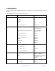
1.2 System Defaults The system defaults are the configuration parameters set in the factory. Use command ‘Clear config’ to restore the defaults. The following table lists some of the basic system defaults.
Flow Control Disabled Port Capability 1000BASE-T – 10 Mbps half duplex 10 Mbps full duplex 100 Mbps half duplex 100 Mbps full duplex 1000 Mbps full duplex Full-duplex flow control disabled Symmetric flow control disabled 1000BASE-SX/LX/LH – 1000 Mbps full duplex Full-duplex flow control disabled Symmetric flow control disabled Rate Limiting Input and Output Limits Disabled Port Trucking LACP (all ports) Disabled Broadcast Storm Protection Status Enabled (all ports) Broadcast Limit Rate 500 pac
IP Settings IP Address 192.168.0.1 Subnet Mask 255.255.255.0 Default Gateway 0.0.0.
1.3 Package Contents The following items are included in the switch’s package: • Switch • AC power cord • RS232 straight-through serial cable for management console port • Rack mount brackets with screws • IntraCore IC3624/48 CD-ROM Contact your dealer immediately if any of these items is missing. 1.4 Front and Back Panel Descriptions The following section describes the front and back panels of the IntraCore IC3624/48 Series switches.
3648 Front Panel Ethernet ports Mini GBIC ports 3648 Rear Panel 12 Asante IntraCore IC3624/48 User’s Manual
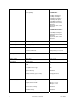
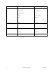
1.4.1 LEDs The IC3624/48 front panel LED display allows you to monitor the status of the switch. The IC3624/48 has one power LED indicator. There are also LED indicators for each of the ports. Refer to the following table for LED information. LED Power 1000MBps 100MBps Link/Activity Color Description Green Power is on. Off Power is off, or main power has failed. Amber A valid 1000 Mbps link has been established on the port. Green A valid 10/100 Mbps link has been established on the port.
Chapter 2: Hardware Installation and Setup Use the following guidelines to easily install the switch, ensuring that it has the proper power supply and environment. 2.1 Installation Overview Follow these steps to install the IntraCore IC3624/48 switch: 1. Open the box and check the contents. See Chapter 1.2 Package Contents for a complete list of the items included with the IntraCore IC3624/48 switch. 2. Install the switch in an equipment or wall rack, or prepare it for desktop placement. 3.
• Do not tamper with the equipment. Doing so could void the warranty • Examine the work area for potential hazards (such as wet floors or ungrounded cables) 2.1.2 Recommended Installation Tools You need the following additional tools and equipment to install the switch into an equipment rack: • Flat head screwdriver • Phillips head screwdriver • Antistatic mat or foam 2.1.3 Power Requirements The electrical outlet should be properly grounded, located near the switch and be easily accessible.
1. Place the switch on a flat, stable surface. 2. Locate a rack-mounting bracket (supplied) and place it over the mounting holes on one side of the switch. 3. Use the screws (supplied) to secure the bracket (with a Phillips screwdriver). 4. Repeat the two previous steps on the other side of the switch. 5. Place the switch in the equipment rack. 6. Secure the switch by securing its mounting brackets onto the equipment rack with the appropriate screws (supplied).
2.4 Connecting Power Important: Carefully review the power requirements (Chapter 2.1.3) before connecting power to the switch. Use the following procedure to connect power to the switch: • Plug one end of the supplied power cord into the power connector on the back of the switch. • Plug the other end into a grounded AC outlet. The power LED show the initialization is in process. The front panel LEDs blink and the power LED illuminates when it has initialized.
determine whether the device at the other end of the link is a hub, switch, or workstation, and adjust its signals accordingly. No crossover cables are required. Although 10/100BaseT requires only pins 1, 2, 3, and 6, you should use cables with all eight wires connected as shown in Table 2-2 below. 1000BaseT requires that all four pairs (8 wires) be connected correctly, using Category 5 or better Unshielded Twisted Pair (UTP) cable (to a distance of 100 meters).
• 1000BaseLZ GBIC: Cables with SC-type fiber connectors; 10µ single-mode fiber media up to 120 km (393,701') • 1000BaseT: Category 5 or better Unshielded Twisted Pair (UTP) cable up to 100 m (328.1') When attaching a workstation to the switch, a standard straight-through CAT5 cable may be used, even when the workstation is attached via a patch panel. No crossover cable is needed with the MDX/MDI ports. The switch should be kept off the network until proper IP settings have been set.
Chapter 3: Initial Software Setup Configure the switch by connecting directly to it through a console (out-of-band management), running a terminal emulation program, such as HyperTerminal or by using telnet. 3.1 Connecting to a Console To connect the switch to a console or computer, set up the system in the following manner: 7. Plug power cord into the back of the switch. 8. Attach a straight-through serial cable between the RS232 console port and a COM port on the PC. 9.
e. Press the Configuration button from the Connect To window. e f. Set the data rate to 9600 Baud. g. Set data format to 8 data bits, 1 stop bit and no parity. h. Set flow control to NONE. f g h Now that terminal is set up correctly, power on the switch. The boot sequence will display in the terminal. After connecting to the console, you will be asked for a password The initial default password for access using either the console or telnet is Asante (case-sensitive).
3.2 Connecting to a PC You can connect to the switch through a PC by using either an Ethernet or USB cable. Using a telnet session, you can telnet into the switch. The default IP address is 192.168.0.1. The case-sensitive default password is Asante. 3.3 Username and Password The default Username/Password is admin/Asante. 3.4 Configuring an IP Address The switch ships with the default IP address 192.168.0.1/255.255.255.0.
3.5 Restoring Factory Defaults To restore the switch to its factory default settings, follow the commands shown in the following screen. COMMAND> enable Switch# clear config Switch# save Important: To retain configuration changes after a system reload you must save changes made in running configuration. From the privileged level, configurations can be saved using the save command. The switch is ready for configuration. Refer to the following chapters for management and configuration information.
Chapter 4: Understanding the Command Line Interface (CLI) The switch utilizes Command Line Interface (CLI) to provide access to several different command modes. Each command mode provides a group of related commands. In general, after typing a command name, always press ‘enter’ to start the execution of the command. After logging into the system, you are automatically in the user top (user EXEC) mode. From the user top mode you can enter into the privileged top (privileged EXEC) mode.
COMMAND> The user top commands available at the user level are a subset of those available at the privileged level. In general, the user top commands allow you ping remote hosts and show port statistics. To list the commands available in user top mode, enter a question mark (?). Use a space and a question mark (?) after entering a command to see all the options for that particular command. Command Purpose ? Lists the user EXEC commands. show ? Lists all the options available for the given command.
COMMAND> enable Username : admin Password : xxxxxx Switch# Command Purpose COMMAND> enable Enters the privileged EXEC mode. Switch# ? Lists privileged EXEC commands. To return to user EXEC mode, use the exit command. To list the commands available in top mode, enter a question mark (?) at the prompt, as shown in the following example. Enter a question mark (?) after a command to see all the options for that command.
4.3 Global Configuration Mode Global configuration commands apply to features that affect the system as a whole, rather than just one protocol or interface. Commands to enable a particular routing function are also global configuration commands. To enter the global configuration mode, use the configure command. The following example shows how to access and exit global configuration mode and list global configuration commands.
log Configure log server radius-server Configure radius server static-address Static address mgmt-accesslist Set management access list, allows up to 8 IP addresses monitor Configure port mirroring dot1x Configure 802.
Switch(Config)# interface 1 Switch(Interface 1)# ? exit Exit current shell dot1x Configure 802.
To get help specific to a command mode, a command, a keyword, or an argument, perform one of the following commands: Command Purpose Help Obtain a brief description of the help system in any command mode. ? List all commands available for a particular command mode. When using context-sensitive help, the space (or lack of a space) before the question mark (?) is significant.
Generally, uppercase letters represent variables. For example, after entering a command, such as hostname, and using a space and a question mark, you will be prompted for the new name, represented by WORD. In cases where an IP address is the variable, the uppercase letters A.B.C.D will represent it. Switch(config)# network parms ? A.B.C.D Enter IP address of the switch In the following access list example, seven further options are listed after the question mark.
sequence to recall successively more recent commands. 4.6 Using Command-Line Editing Features and Shortcuts A variety of shortcuts and editing features are enabled for the CLI command-line interface.
4.6.2 Completing a Partial Command Name If you cannot remember a complete command name, press the Tab key to allow the system to complete a partial entry. Keystrokes Purpose Enter the first few letters and press Tab. Complete a command name. In the following example, when you enter the letters “conf” and press the Tab key, the system provides the complete command: Router# conf Router# configuration The command is not immediately executed, so that you may modify the command if necessary.
Chapter 5: Managing the System and Configuration Files This chapter explains how to manage the system information, as well as how to manage the configuration files for IntraCore 3624/48. 5.
5.1.2 Specify the Hostname The factory-assigned default host name is Switch. To specify or modify the host name for the network, use the Network sysinfo sysname global configuration command. Command Purpose Network sysinfo sysname name This systems hostname. 5.1.5 Test Connections with Ping Tests The switch supports IP ping, which can be used to test connectivity to remote hosts, via their IP addresses. Ping sends an echo request packet to an address and “listens” for a reply.
Switch# show running-config 5.2 Managing Configuration Files This section discusses how to download configuration files from remote servers, and store configuration files on the switch at system startup. Configuration files contain the commands the switch uses to customize the function of the IC3624/48. The setup command facility helps you create a basic configuration file. However, you can manually change the configuration by typing commands in a configuration mode. 5.2.
Switch# copy nvram_config tftp 192.168.123.100 file Specify a filename Switch# copy nvram_config tftp 192.168.123.100 file WORD Enter filename for backup configuration Switch# copy nvram_config tftp 192.168.123.100 file July Switch# copy nvram_config tftp 192.168.123.100 file July Switch# 5.2.3 Copying Configuration Files from a Network Server to the Switch You can copy configuration files from a TFTP server to the running configuration of the switch.
Switch# clear config Don’t forget to use ‘save’ command to preserve the new configuration across reboots. 5.3 Managing system image Files This system image file is stored in the non-volatile flash in the switch. It is the software that runs in the switch after power up. It provides user interfaces (CLI, Web, telnet) for user to control and manage the switch.
5.4.1 Configuring SNMP Support The Simple Network Management Protocol (SNMP) system consists of three parts: an SNMP manager, an SNMP agent, and a Management Information Base (MIB). SNMP is an application-layer protocol that allows SNMP manager and agent stations to communicate. SNMP provides a message format for sending information between an SNMP manager and an SNMP agent. The agent and MIB reside on the switch.
• Define SNMP Trap Operations Command Purpose snmp trapstation add 192.168.123.100 community public type linkchange trap-version 1 Create a trap host 192.168.123.100 to which the switch can send version 1 link change trap messages using community string ‘public’. 5.5 Spanning Tree Algorithm The Spanning Tree Protocol (STP) is part of the IEEE 802.1D standard. It provides for a redundant network without the redundant traffic through closed paths.
Each bridge should receive regular configuration BPDUs from the direction of the root bridge. If the maximum age timer expires before the bridge receives another BPDU, it assumes that a change in the topology has occurred, and it begins recalculating the spanning tree. The default setting for Maximum Age is 20 seconds.
• Designated port—connects to the designated switch, which has the lowest path cost when forwarding packets from that LAN to the root bridge. The port through which the designated switch is attached to the LAN is called the designated port. • Alternate port—offers an alternate path toward the root switch to that provided by the current root port. • Backup port—acts as a backup for the path provided by a designated port toward the leaves of the spanning tree.
Configuring Switch/Bridge Priority For the range is 0 to 61440 in increments of 4096; the default is 32768. The lower number is used when you want to specify the switch as the root switch. Valid priority values are 0, 4096, 8192, 12288, 16384, 20480, 24576, 28672, 32768, 36864, 40960, 45056, 49152, 53248, 57344, and 61440. All other values are rejected.
The default setting is no edge port configuration. To return the switch to its default setting, use the following configuration command.
For , the range is 0–240 in increments of 16; the default is 128. The lower the number, the higher the priority.
Chapter 6: Configuring IP The Internet Protocol (IP) is a packet-based protocol used to exchange data over computer networks. All other IP protocols are built on the foundation. IP is a network-layer protocol that contains addressing and control information that allows data packets to be routed. The table below lists the traditional classes and ranges of IP addresses and their status. Class Address or Range Status A 0.0.0.0 1.0.0.0 to 126.0.0.0 127.0.0.0 Reserved Available Reserved B 128.0.0.
/19 32 Class C 8,192 Hosts /18 64 Class C 16,384 Hosts /17 128 Class C 32,768 Hosts /16 256 Class C OR 1 Class B 65,536 Hosts /13 2,048 Class C 524,288 Hosts 6.1 Establish Address Resolution A device in the IP can have both a local address (which uniquely identifies the device on its local segment or LAN) and a network address (which identifies the network to which the device belongs).
6.2 Managing IP Multicast Traffic Multicast traffic is a means to transmit a multimedia stream from the Internet (a video conference, for example) without requiring a TCP connection from every remote host that wants to receive the stream. Traditional IP communication allows a host to send packets to one host (unicast transmission) or to all hosts (broadcast transmission). IP multicast provides a third scheme, allowing a host to send packets to a group of hosts (group transmission).
Enable the IGMP querier Multicast switches can send IGMP host-query messages to discover which multicast groups are present on attached networks. These messages are sent to the all-systems group address of 224.0.0.1 with a time-to-live (TTL) value of 1. Multicast switches continue to periodically send host-query messages to refresh their knowledge of memberships present on their networks.
6.3 Access Lists An access list is a criteria statement that the switch uses to determine whether to allow or block traffic based on MAC addresses, IP addresses, or UDP/TCP ports. Access lists can be configured to provide basic security on your network, and to prevent unnecessary traffic between network segments. Access lists are applied to inbound traffic only. When configuring an access list, an argument of ‘priority’ must be specified.
Command Purpose access-list name acl1 set …… Set the criteria statement of an access list named ‘acl_name’ access-list name acl1 action …… Specify the action to take if criteria of the access list is matched In the following example, an access list will be created to block traffic sent from MAC address 00-00-94-12-34-56.
6.3.3 Applying an Access List to an Interface After creating your access lists, you can choose interfaces for which the access lists will be applied. If no interfaces are explicitly selected, the access list is applied to all interfaces.
Chapter 7: VLAN Configuration VLANs are used to organize any group of network nodes into separate broadcast domains. VLANs confine broadcast traffic to the originating group and eliminate broadcast storms in large networks. VLANs provide a secure and efficient network environment. VLANs are based on untagged port groups, or traffic can be explicitly tagged to identify the VLAN group to which it belongs. Untagged VLANs can be used for small networks attached to a single switch.
number Enter a VLAN ID range Enter a range of VLAN ID Switch(Config)# vlan add number <2..4094> Enter a VLAN ID Switch(Config)# vlan add number 2 Switch(Config)# VLANS can be configured using the following commands: vlan add number 2 Create vlan 2 vlan add range from 3 to 6 Create vlans 3,4,5,6 vlan delete 3 Delete vlan 3 7.2 VLAN Port Membership Ports of VLANS can be configured by the commands below : 7.2.
Switch(Config)# vlan add number 4 Switch(Config)# vlan port ports port-configure 2 untagged 11-14 Switch(Config)# vlan port ports port-configure 1 exclude 11-14 Switch(Config)# 7.2.2 Trunk (IEEE 802.1q) By default, a trunk port is a member of all VLANs. Use the following commands, beginning in configuration mode, to assign an IEEE 802.1q trunk port: Command Purpose interface IFNUMBER Enter the interface number to access the interface configuration mode.
The trunk port accepts tagged and untagged frames. All the untagged frames are classified to the trunk port’s native VLAN (the VLAN whose VID matches the port’s PVID). The trunk port also sends out the frames as untagged for the native VLAN and tagged for other VLANs.
Chapter 8: Quality of Service Configuration Quality of Service (QoS) is a general term referring to various methods of traffic management you can employ on your network to ensure that traffic you identify as high-priority can use a sufficient share of the available bandwidth. The IC39240/480 internally has 4 COS queues per port with which a wide varieties of applications (Video/Audio) can be supported. In QOS, packets are classified by the priority assigned to them.
Command Purpose Switch#qos scheduling [wrr | strict] Set the scheduling method. Switch#qos wrr ….. Set the settings of the weighted round robin. 8.1.2 Monitoring Weighted Round Robin To display information about weighted round robin settings, use the following command in EXEC mode: Command Purpose show qos queue-settings Displays the settings of the weighted round robin. 8.2 Priority Queuing Priority Queuing (PQ) allows you to define how traffic is prioritized in the switch.
To change priority-queue mapping, use the following command in EXEC mode: Command Purpose Switch#qos cos …… Set the mapping between 802.1P priorities and 4 internal queues 8.2.2 Port Based QOS To set Port Based QOS, use the following command in EXEC mode: Command Purpose Switch#qos port-based …. Set the priority of the port 8.2.3 802.1P Based QOS A packet with an 802.1P header has a priority value which will be assigned to the packet by the switch. 8.2.
8.3 Traffic Shaping Traffic shaping allows you to control the traffic going out from an interface in order to match its flow to the speed of the remote target interface Thus, traffic adhering to a particular profile can be shaped to meet downstream requirements, thereby eliminating bottlenecks in topologies with data-rate mismatches. 8.3.
Chapter 9: Configuring the Switch Using the GUI This chapter provides and overview of configuring the switch with the graphical user interface (GUI). For more information about the different features and how to implement them refer to the chapters specific to that function. At your web browser enter the IP address for the switch to launch the GUI. Depending on settings, you may receive a certificate error message. Ignore this and continue. The defaults are: IP Address: 192.168.0.
9.1 Main Configuration Menu Use the navigation panel on the left side of the GUI screen to configure the switch. From this panel you can access the following screens: • System • Port Management • VLAN Management • Spanning Tree • Multicast • Security • QoS • SNMP • LLDP • Admin • Statistics • Help • Logout The following example shows the main Configuration Menu.
9.2 System Use this section to access general information about the switch. 9.2.1 System System Information With the first system screen up a name and location for the switch can be added. A system contact can also be entered. You can also view the Hardware Version, Boot Version, Firmware Version, Build Date and the MAC Address. Save the settings when done by clicking the “Save Settings” button.
9.2.2 System Network management. This page allows the setting of static IP information. The switch can also be set to receive an address automatically from a DHCP server. The switch ships with the default IP address 192.168.0.1. Click the “Save Settings” button when done. The Internet Protocol (IP) is a packet-based protocol used to exchange data over computer networks. All other IP protocols are built on the foundation.
The table below lists the traditional classes and ranges of IP addresses and their status. Class Address or Range Status A 0.0.0.0 1.0.0.0 to 126.0.0.0 127.0.0.0 Reserved Available Reserved B 128.0.0.0 to 191.0.0.0 255.255.255.0 Available C 192.0.0.0 to 223.255.255.0 Available D 224.0.0.0 to 239.255.255.255 Multicast group addresses E 240.0.0.0 to 255.255.255.254 255.255.255.
9.2.3 System Time Setting Use the Time Setting page to set the time zone or local time for the switch. Daylight savings can also be enabled. Click the “Save Settings” button when done.
9.2.4 System – Green Ethernet. Green Ethernet is a power saving technology that allows the switch to save power when Ethernet is not being actively used.
9.3 Port Management – Port Config The Port Management section displays assorted settings for each port. Port Management – Port Config - Specific Port. Settings can be made on a per port basis. When a port number is clicked the subscreen appears.
Port management – LACP Property. The LACP properties are displayed on this screen. The system LACP Priority can be set here. By clicking on a port number, a subscreen for each port is available. Port Management – LACP Property – Port. Settings for each port can be entered.
Port Management – LAG Group. Click on a group number to set the groups properties. Port Management – LAG Group - Each Group. Once a link aggregation group is specified, the screen below can be used to add ports to the group. 9.4 VLAN Management. VLANs are used to organize any group of network nodes into separate broadcast domains. VLANs confine broadcast traffic to the originating group and eliminate broadcast storms in large networks. VLANs provide a secure and efficient network environment.
VLANs are based on untagged port groups, or traffic can be explicitly tagged to identify the VLAN group to which it belongs. Untagged VLANs can be used for small networks attached to a single switch. Tagged VLANs should be used for larger networks, and all the VLANs assigned to the inter-switch links. A VLAN is a group of end stations with a common set of requirements, independent of physical location.
VLAN MANAGEMENT – VLAN SETTINGS. With a vlan selected, ports can be marked as tagged, or untagged. Lover on the screen, LAG groups can also be tagged or untagged. Click Save Settings when done.
VLAN MANAGEMENT – VLAN PORT. This screen allows additional settings to be controlled on a per port basis. Here the PVID can be changed to. Changing the PVID in required to force the port to respond to a particular VLAN. Becoming a member of a VLAN is only the start. The port PVID must be changed to cause it to respond only to the desired VLAN. Various filters can be set on this screen. Ingress filter, Non 802.1Q filter, and port protection can all be set here.
9.5 Spanning Tree. RSTP (Rapid spanning tree protocol) can be enabled at this screen. Various timer settings can also be set. Use this screen to change the priority and the path cost for specific ports. The priority default value is 128, and the value range is 0–240 (in multiples of 16). The lower the assigned port path cost is, the more likely that port will be accessed.
Use this screen to change the priority and the path cost for specific ports. The priority default value is 128, and the value range is 0–240 (in multiples of 16). The lower the assigned port path cost is, the more likely that port will be accessed. The default port path cost for a 10 Mbps or 100 Mbps port is the result of the equation: Path cost = 1000/LAN speed (in Mbps) Therefore, for 10 Mbps ports, the default port path cost is 100. For 100 Mbps ports, it is 10.
MSTP. Multiple Spanning Tree Protocol can be enabled on this page. Individual Port properties can be manipulated at this screen.
MST Instance parameters can be modified on the following two screens.
9.6 Multicast. Static multicast settings can be set. Port by port participation can be controlled.
IGMP The Internet Group Management Protocol (IGMP) manages the multicast groups on a LAN. IP hosts use IGMP to report their group membership to directly connected multicast switches. Switches executing a multicast routing protocol maintain forwarding tables to forward multicast datagrams. Switches use the IGMP to learn whether members of a group are present on their directly attached sub-nets. Hosts join multicast groups by sending IGMP report messages.
9.7 Security - Port Security. Each port can be listed individually or a table can be displayed using the Show Table button Access control lists can be established using this screen.
802.1X can be enabled on a per port basis Radius server can be identified at this screen. A secret key can be created and the port can be altered.
TACAS+ and Storm Control are available on the next screens.
Management IP list can be used to enter a list of IP addresses to limit the availability of switch Management. Auto DoS provides protection from a variety of denial of service type of threats.
9.8 QoS. Quality of service settings allow various protocols to be selected to protect functions that require real time performance and limit other traffic.
DSCP can be implemented on this page. There are eight queues available numbering 0 – 7. Click on the Mode selector to choose DSCP. Then settings will be available to assign DHCP codes to the eignt queues.
802.1P priory is supported to four queues. Each priority level can be assigned to one of the four queues.
Port-based QoS allows the priority for each port to be manually set. Click the Update button when done to save changes.
Rate Control allows traffic shaping for each port. An ingress rate limit can also be set.
9.9 SNMP Various screens are available to enable and manipulate SNMP. Profiles can be set for users, communities, and groups. SNMP allows network managers to obtain specific performance and configuration information from a software agent on a remote-network device. SNMP allows different types of networks to communicate by exchanging network information through messages known as protocol data units (PDUs). The IntraCore IC3624/48 supports SNMPv1, v2 and v3.
SNMP Continued 90 Asante IntraCore IC3624/48 User’s Manual
9.
Asante IntraCore IC3624/48 User’s Manual
9.11 Admin - Admin Password Admin password is the screen that can be used to change the password. Remember to click Save Settings when done. L2 Table makes available MAC addresses and lists the port they are associated with. Aging time can also be specified.
Static addresses can be added using this screen. Dynamic ARP is the screen that allows aging time and trusted ports to be set on a per port basis. Click Save Setting when done.
Port Mirroring – To set up a mirror, identify the port to be mirrored by checking the ingress mirror, or egress mirror for the port. Next select the port to mirror the information to. Admin Timeout allows the timeout in seconds to be set before the management session is terminated do to no activity.
ADMIN Continued – assorted administration functions are controlled using the next several screens.
Asante IntraCore IC3624/48 User’s Manual
Asante IntraCore IC3624/48 User’s Manual
Asante IntraCore IC3624/48 User’s Manual
Cable diagnostic a cable test that can be run for each port.
DHCP Relay/ DCP Option 82 – these screens control the relay of DHCP information from a server. VLANS can also be specified to receive DHCP information.
9.12 Statistics RMON information and settings are controlled using the next screens. General counters and timers are also displayed.
Asante IntraCore IC3624/48 User’s Manual
Asante IntraCore IC3624/48 User’s Manual
Asante IntraCore IC3624/48 User’s Manual
9.13 Help General help is available for many screens.
9.14 Logout Use this screen to logout and close the session.
Asante IntraCore IC3624/48 User’s Manual
Chapter 10: CLI Commands The CLI is divided into various modes. The Commands in one mode are not available until the operator switches to that particular mode. The commands available to the operator at any point in time depend upon the mode. Entering a question mark (?) at the CLI prompt, and displays a list of the available commands and descriptions of the commands. The CLI provides the following modes. 10.1 Modes When the operator logs into the CLI, the User Mode is the initial mode.
Format ping Mode User Mode 10.2.5 show 1) show port This command displays port status. Format show port { | all} Mode User Mode 2 ) show network This command displays switch IP configuration Format show network Mode User Mode 3) show system This command displays system information. Format show system Mode User Mode 4) show port statistics This command displays port statistics. Format show port statistics { | all} Mode User Mode 10.2.
Format clear igmpsnooping Mode Privileged Mode 10.3.2.5 clear static-mcast This command is used to clear static multicast groups Format clear static-mcast Mode Privileged Mode 10.3.2.6 clear pass This command is used to restore administrator’s password to factory default Format clear pass Mode Privileged Mode 10.3.2.7 clear lacp This command is used to restore LAG and LACP configuration to factory default Format clear lacp Mode Privileged Mode 10.3.2.
This command is used to exit current shell Format logout Mode Privileged Mode 10.3.8 ping This command is used to proceed ping destination host Format ping Mode Privileged Mode 10.3.9 reload This command is used to reboot system Format reload Mode Privileged Mode 17 10.3.10 save This command is used to save configuration Format save Mode Privileged Mode 10.3.11 show This command is used to show configured data 10.3.11.
This command display dot1x and port configuration Format show dot1x config Mode Privileged Mode 2) show dot1x radius This command display radius configuration Format show dot1x radius Mode Privileged Mode 3) show dot1x statistics This command display dot1x statistics Format show dot1x statistics Mode Privileged Mode 10.3.11.
4) show lldp msap-entry This command is used to display msap details information Format show lldp msap-entry <1..26> Mode Privileged Mode 10.3.11.7 show logging This command is used to display trap records 1) show logging memory-log This command display memory log Format show logging memory-log Mode Privileged Mode 2) show logging flash-log This command display flash logs Format show logging flash-log Mode Privileged Mode 10.3.11.
This command is used to display switch running config Format show running-config Mode Privileged Mode 10.3.11.14 show snmp This command is used to display all snmp config 1) show snmp groups This command display all snmp groups Format show snmp groups Mode Privileged Mode 2)show snmp users This command display all snmp users Format show snmp users Mode Privileged Mode 3) show snmp communities This command display all snmp communities Format show snmp communities Mode Privileged Mode 10.3.11.
10.3.11.18 show sysinfo This command is used to display system information including system up time Format show sysinfo Mode Privileged Mode 10.3.11.
Format Show rmon alarm Mode Privileged Mode Show rmon event log This command displays rmon event log. Format Show rmon event log event index <1..65535> Mode Privileged Mode 23 6) Show rmon history This command displays rmon history. Format Show rmon history index <1..65535> Mode Privileged Mode 7)Show rmon statistics This command displays port rmon statistics. Format Show rmon statistics Mode Privileged Mode 10.3.12 telnet This command telnet the other host. Format telnet
This command is used to forward frame and learn SA into ARL table Format vlan ingress bypass Mode Global Config 10.4.2.4 vlan port This command is used to configure 802.
10.4.5 link-aggregation This command is used to configure link aggregation 10.4.5.1 link-aggregation addport This command is used to configure LAG groups Format Link Aggregation addport lag Mode Global Config 10.4.5.
10.4.7 Log This command is used to configure log server 10.4.7.1 Log log-server This command is used to configure log server 1) Log log-server name add This command is used to specify log server name, enter a name, up to 12 characters, add a log server IP address Format Log log-server name add ipaddr word Mode Global Config 2) Log log-server name delete This command is used to delete a log server 27 Format log log-server name delete Mode Global Config 10.4.7.
Mode Global Config 28 10.4.10.3 mgmt-accesslist disable This command disables management access list. Format mgmt-accesslist disable Mode Global Config 10.4.11 monitor commands 10.4.11.1 monitor enable This command enables port mirroring. Format monitor enable Mode Global Config 10.4.11.2 monitor disable This command disables port mirroring. Format monitor disable Mode Global Config 10.4.11.3 monitor des Configure destination port.
Format network mgmt-vlan Mode Global Config 10.4.13.2 network parms This command configures static IP address of the switch. Format network parms Mode Global Config 10.4.19 network protocol This command configure switch dhcp client. Format network protocol {dhcp|none} Mode Global Config 10.4.13.4 network dhcp-relay Configure switch dhcp relay functions. 1) network dhcp-relay mode This command configures dhcp relay mode.
This command configures ports auto-negotiation mode. Format port-all auto-negotiate {enable|disable} Mode Global Config 10.4.14.3 port-all flow-control This command configures ports flow control. Format port-all flow-control {enable|disable} Mode Global Config 10.4.14.4 port-all portsec-lockmode Configure port security. 1) port-all portsec-lockmode none This command disable port security.
Format port-all Storm-Control broadcast-multicast Mode Global Config 4) port-all storm-control broadcast-unknown This command configures storm control for broadcast and unknown unicast. Format port-all storm-control broadcast-unknown Mode Global Config 5) port-all storm-control all-cast This command configures storm control for broadcast, multicast and unknown unicast. Format port-all Storm-Control all-cast Mode Global Config 10.4.15 qos commands 10.4.15.
Mode Global Config 10.4.16 set commands 10.4.16.1 set IGMP Configure IGMP snooping. 1) set igmp enable This command enables igmp snooping. Format set igmp enable Mode Global Config 2) set igmp disable This command disables IGMP snooping. Format set igmp disable Mode Global Config 3) set igmp last-memberquery This command specifies last member query interval. Format set igmp last-memberquery <1-200> 33 Mode Global Config 4) set igmp last-membercount This command specifies last member count.
Mode Global Config 10.4.17 snmp commands 10.4.17.1 snmp notify This command configures snmp notification. Format snmp notify {enable|disable} Mode Global Config 34 10.4.17.2 snmp group 1) snmp group add This command create a snmp group. Format snmp group add version <1-2> Mode Global Config 2) snmp group delete This command delete a snmp group. Format snmp group delete Mode Global Config 10.4.17.3 snmp user 1) snmp user add This command creates a snmp user.
Mode Global Config snmp trapstation add community type none Send no trap. Format snmp trapstation add community type none trap-version {1-2} Mode Global Config 2) snmp trapstation delete This command delete a trap station. Format snmp trapstation delete Mode Global Config 10.4.18 sntp commands 10.4.18.1 sntp daylight This command enables or disables the daylight saving configuration. Format sntp daylight {enable|disable} Mode Global Config 10.4.
3) spanning-tree forceversion none This command selects none spanning tree type. Format spanning-tree forceversion none Mode Global Config 10.4.110.2 spanning-tree configuration This command configures MSTP region name and revision. 1) spanning-tree configuration name This command configures MSTP region name (Max.32 chars). Format spanning-tree configuration name Mode Global Config 2) spanning-tree configuration revision This command configures revision level.
10.4.110.8 spanning-tree mst Configure a multiple spanning tree instance. 1) spanning-tree mst instance This command creates or removes a MST instance spanning-tree mst instance add This command creates a MST instance. Format spanning-tree mst instance add vlan mstpid Mode Global Config e.g.
This command creates rmon alarm entry. Format rmon alarm index < 1..65535 >interval<0..3600>interfacecounter<1..17>sample{absolute|delta}start{rasing|falling|all}rthreshol d<0..65535>fthreshold<0..65535> reindex <0..65535> feindex<0..65535> owner< WORD> Mode Global Config e.g. Switch(Config)# RMON alarm index 1 interval 10 interface counter 1 sample delta start all rthreshold 100 fthreshold 10 reindex 1 feindex 0 owner test 10.4.22.
This command clears TCP/UDP destination port filter. Format access-list name clear l4port DST port 40 Mode Global Config 4) access-list name clear packet-type This command clears packet type filter. Format access-list name clear packet-type Mode Global Config 5) access-list name clear mac SA This command clears a source mac address. Format Access-list name clear mac SA Mode Global Config 6) access-list name clear MAC DA This command clears a destination mac address.
access-list name set l4port DST-port This command specifies the destination TCP/UDP port range. Format access-list name set l4port DST-port from <1-65535> to <1-65535> Mode Global Config 4) access-list name set IP-mode packet-type This command specifies the packet type. Format access-list name set IP-mode packet-type {ICMP|IGMP|IP|TCP|UDP|GRE} Mode Global Config 5) access-list name set mac-mode Specify ACL entry priority.
Format arp static {add|delete} vid <1~4094> ip mac Mode Global Config 10.4.25 dos Commands Note: This commands only support on GG24 GIGABIT PORTS WITH 2 SHARED MINI-GBIC SLOTS/G44 GIGABIT PORTS WITH 4 SHARED MINI-GBIC SLOTS L2 MANAGEMENT SWITCH/G48 100BASETX + 4 GIGABIT COMBO WITH 2 SHARED MINI-GBIC SLOTS LAYER 2+ MANAGEMENT SWITCH) 10.4.25.1 dos land This Command enables and disables land-type attacks prevention. Format dos land {enable|disable} Mode Global Config 10.4.25.
e.g. switch(interface g1)#lacp admin 36768 10.5.3.2 priority command Configure lacp port priority Format lacp priority <0..65535> Mode Interface Config 10.5.4 addport command add one port to a LAG group Format addport Mode Interface Config 10.5.5 delport command Remove a port from a LAG group Format delport Mode Interface Config 10.5.6 lldp command An lldp agent can transmit information about the capabilities and current status of the system associated with its MSAP identifier.
Mode Interface Config 10.5.7 admin-mode Configure administrative mode on a port Format Switch(Interface 1)# admin-mode {enable|disable} Mode Interface Config 10.5.8 auto-negotiate 45 Configure auto-negotiate mode on a port Format auto-negotiate {enable|disable} Mode Interface Config 10.5.9 speed Set port speed to 10Mbps half duplex/ 10Mbps full/ 100Mbps half/ 100Mbps full/ 1000Mbps 100FX mode/1000base-x full . Format speed {10hd|10fd|100hd|100fd|1000fd|100fx|1000base-x} Mode Interface Config 10.5.
and 0 means no limit. Format storm-control broadcast Mode Interface Config 10.5.14.3 storm-control broadcast-multicast This command storm control limited value :0,64,256,1024,10240,65536.102400,1024000,which the unit is Kbps and 0 means no limit. Format storm-control broadcast-multicast Mode Interface Config 10.5.14.4 storm-control broadcast-unknown This command storm control limited value :0,64,256,1024,10240,65536.102400,1024000,which the unit is Kbps and 0 means no limit.
This command configure the port priority on a MST instance:0~4096. Format spanning-tree mst priority <1 4096> Mode Interface Config 10.5.17.6 spanning-tree participation This command configures RSTP capability on a port. Format spanning-tree participation {enable|disable} Mode Interface Config 10.5.17.7 spanning-tree priority this command configure RSTP port priority:0~240 format spanning-tree priority <0..240> mode Interface Config 10.5.18 VLAN command 10.5.18.
Appendix A: Basic Troubleshooting In the unlikely event that the switch does not operate properly, follow the troubleshooting tips below. If more help is needed, contact Asante’s technical support at www.asante.com/support. Problem Possible Solutions The Power LED is not lit. Check the power connection. Plug the power cord into another known working AC outlet. The primary power supply has failed. Install the optional external power supply and have the primary power supply serviced as soon as possible.
Appendix B: Specifications The sections below list the features and product specifications for the IntraCore IC3624/48 switch. Interfaces - 24/48 RJ-45 connectors for 10/100 BASE-T - 2/4 RJ45 Combo Ports for 1000 BASE T with 2 MiniGIBC/SFP Slots - IEEE Auto Negotiation or manual configuration - Reset button - RS232 Console port Status Indicators - Power Operating status of the unit - LED for port link/activity Performance Specifications - Wire-speed, Gigabit Ethernet Switch at 6.
L2+ Management Specifications - Command Line Interface/Web /Telnet - GVRP VLAN Negotiation - ACL for L2,L3 and L4 - SSl and SSH - TACACS+ Client Authentication - IGMP Snooping and IGMP Proxy - DHCP Client and DHCP Relay Physical - Dimensions (WxDxH): 430 x 250 x 44 (mm), 16.9 x 7 x 1.7 (inch) - Weight: 3.5 kg(6.
Appendix C: FCC Compliance and Warranty Statements C.1 FCC Compliance Statement This equipment has been tested and found to comply with the limits for a Class A digital device, pursuant to part 15 of the FCC Rules. These limits are designed to provide reasonable protection against harmful interference when the equipment is operated in a commercial environment.
C.3 IntraCore Warranty Statement Products: IntraCore IC3624/48 Subject to the limitations and exclusions below, Asante warrants to the original end user purchaser that the covered products will be free from defects in title, materials and manufacturing workmanship for a period of three years from the date of purchase. This warranty excludes fans, power supplies, nonintegrated software and accessories.
Index Cabling VLAN ....................................................................71 console .................................................................20 Ethernet ................................................................18 weighted fair queuing ...........................................57 Connecting procedures............................................................17 console ...........................................................13, 20 CLI network .........................
context sensitive ...................................................30 IGMP weighted fair queuing ...........................................57 Rapid Spanning-Tree configuration .........................................................48 edge port ..............................................................43 host-query ......................................................49, 79 link type ................................................................43 overview ..................................
bandwidth .............................................................57 monitoring...........................................57, 58, 59, 60 configuration .........................................................