IntraCore™ 65120 Series Gigabit Ethernet Switches User’s Manual
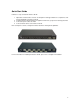
Quick Start Guide Follow these steps to install the IntraCore 65120: 1. 2. 3. 4. Open the box and check the contents. See Chapter 2.1 Package Contents for a complete list of the items included with your IntraCore 65120. Install the IntraCore 65120 switch in an equipment or wall rack, or prepare it for desktop placement. Connect the power cord to the switch. Connect network devices to the IntraCore 65120. Refer to Chapters 3 and 4 to configure the IntraCore 65120 for management capabilities.
IntraCore™ 65120 Series Gigabit Ethernet Switches User’s Manual Asanté Technologies, Inc. 821 Fox Lane San Jose, CA 95131 USA SALES 800-662-9686 Home/Office Solutions 800-303-9121 Enterprise Solutions 408-435-8388 TECHNICAL SUPPORT 801-566-8991 Worldwide 801-303-3787 FAX www.asante.com support@asante.com Copyright © 2001 Asanté Technologies, Inc. All rights reserved.
Table of Contents Quick Start Guide 2 Chapter 1 Introduction 6 1.1 Front Panel Descriptions 1.2 LED Definitions 1.3 Management Chapter 2 Installation and Setup 2.1 Package Contents 2.2 Installation Overview 2.3 Setup 2.4 Password Protection 2.5 IP Assignment 2.6 SNMP Host Access Chapter 3 Web-Based Management 3.1 Web Pages 3.2 Introduction 3.3 System Manager 3.4 Port Manager 3.5 Address Manager 3.6 Spanning Tree 3.7 VLAN Setup 3.8 Port Trunking 3.9 Port Mirroring 3.
Appendix D: FCC Compliance and Safety Statements 46 Appendix E: Online Warranty Registration 47 5
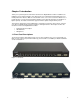
Chapter 1 Introduction Thank you for purchasing the Asanté IntraCore 65120 Series Gigabit Ethernet switch. In addition to the traditional console and telnet interface, this switch can also be configured and managed through a userfriendly web browser interface. With an on-board HTTP server, users can access the box with the use of popular browsers such as Netscape Navigator and Microsoft I.E (Netscape Navigator 4.0 and IE 4.01 or higher required).
1.
1.3 Management There are three different methods by which a user can manage the switch: web, console/telnet, or SNMP. 1.3.1 Web-Based Interface Users can configure the switch, monitor the LED panel, and display statistics graphically with Netscape Navigator browser version 4.0 or higher and Microsoft IE version 4.01 or higher. With Internet access, users can link directly to the local switch’s home page. Detailed description is found in Chapter 3 Web-Based Management. 1.3.
1.3.4 Management Information Bases (MIBs) The system supports the following MIBs: 1. MIB II (RFC 1213) 2. Ethernet Interface MIB (RFC 1643) 3. Bridge MIB (RFC 1493) 4. 4 groups of RMON (RFC 1457) • The Ethernet Statistics Group • The Ethernet History Group • The Alarm Group • The Event Group 5.
Chapter 2 Installation and Setup This chapter provides the following information: • • • • • • Package Contents Installation Setup Password Protection IP Assignment SNMP Host Access 2.
• Examine your work area for potential hazards (I.e. wet floors, ungrounded cables, etc. 2.2.2 Recommended Installation Tools You will need the following tools and equipment (not included) to install the IntraCore 65120 switch: • • Number 1, number 2 and 3/16-inch flat-blade screwdrivers Antistatic mat or foam 2.2.3 Power Requirements The electrical outlet should be located near the IntraCore 65120 and be easily accessible. It must also be properly grounded.
2.2.7 Equipment Rack Guidelines • • • Size: 17.25 x 10.0 x 1.7 inches 423 x 245 x 43 mm Ventilation: Ensure that the rack is installed in a room where the temperature remains below 40° C (104° F). Be sure that there are no obstructions, such as other equipment or cables, blocking airflow to or from the IntraCore 65120 vents. Clearance: In addition to providing clearance for ventilation, ensure that there is adequate clearance for servicing the IntraCore 65120 from the front. 2.
2.4 Password Protection The Password Protection feature is disabled by default, allowing immediate access to ANYONE on the network. To protect your switch from unauthorized changes to the configuration, you must enable the protection feature. It can only be enabled through the console interface. To set a password via telnet, follow these steps: Note: Use the arrow keys to move within a menu. Press Enter to proceed, and press the Esc. Key to return to the previous screen.
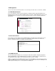
4. 5. 6. Now enter your password, pressing Enter when done. Enter the password again to confirm, pressing Enter when done. Press Ctrl+W to save. 2.5 IP Assignment To assign an IP address (other than the default IP address): 1. 2. From the Main Menu, select a. System Manager. Select b. IP address. 3. In the first field enter the proper IP address for this system (consult your network administrator). 4. 5. Enter the address of the default gateway for the network to which the switch is attached.
6. 7. 8. Press Ctrl-W when done to save these changes. After making IP changes, the system needs to be reset. Press the Esc key to return to the System Manager Menu. Go to System Manager/Reset. Use the arrow keys to select Yes to proceed with Reset. 2.6 SNMP Host Access When the reset is complete the box should be seen on the network. If not, check the IP information again with your network administrator to ensure that all the data is correct.
Chapter 3 Web-Based Management Web-Based Management allows switch configuration changes to be made using an Internet Web browser. This interface also allows for system monitoring of the Switch. Buttons featured are: • • Reload: Pulls that screen’s data from current values on the system Apply: Submits change request to system and refreshes screen data Please refer to Chapter 6 Switching Concepts to review any features that are not familiar to you. 3.
3.2 Introduction This page briefly describes the web-based management features, device management and Interface operation. It contains a product overview and product features. 3.3 System Manager The system manager contains all system operations and general information.
3.3.2 IP Settings There are three tunable parameters to be set by the system administrator: • • • Enter site-specific IP address, Gateway address and Network mask Click Apply to change the IP settings Save Configuration to NVRAM and reset the system to implement the changes 3.3.3 NVRAM Admin After making any changes to the screens within the Web Interface, users must save the changed settings to Non-Volatile Random Access Memory (NVRAM).
3.3.4 Firmware Update On the Firmware Update screen, the system can be configured to download and boot from a new image off the network (Please refer to Chapter 5 when updating software). Choose from the following options: Net option: This option allows the user to try out a new image before upgrading. It requires a TFTP server and a server IP address to retrieve the specified image from the given IP address. The new image will not overwrite the one in the flash (This option is the default setting.).
3.4 Port Manager This page will allow access to the port parameters. The configurable parameters are available as follows: • • • • • • Port Name Port Enable Auto Negotiation Operating Parameters Flow Control HOL Blocking 3.5 Address Manager The Address Manager allows you to add or remove static address entries as well as change the dynamic address aging times. 3.5.
Remove an existing entry: • • Highlight that entry in the table, by clicking on the MAC address Choose Remove 3.5.2 Address Aging Aging Time is a variable that must be configured. Its purpose is to determine the amount of time an entry is held in the forwarding tables. The default value is set to 300 seconds (5 minutes). • • The administrator may change this value to any value between 10 and 1,000,000 seconds After changing the value, click Apply 3.
3.6.2 Port Settings For the Port Settings options, you can specify spanning tree parameters for each port. These parameters include port priority and path cost. 3.7 VLAN Setup The VLAN tagging option is a standard set by the IEEE to facilitate the spanning of Virtual Local Area Networks (VLANs) across multiple switches (Reference: IEEE standard 802.1Q-1998 Virtual Bridged Local Area Networks). This page has two options: Membership and PVID Settings. 3.7.
Add VLAN Membership: • • Select the VLAN you want to modify Click the box below the port number on the line of the VLAN, so that a “T” (tagged) or “U” (untagged) appears Remove VLAN Membership: • Click the box again until a blank box appears. This will remove VLAN membership from the port 3.7.2 Port VLAN ID (PVID) Settings All untagged packets entering the switch will by default be tagged with the ID specified by the port’s PVID.
3.9 Port Mirroring Port mirroring is a feature to help in the debugging of a network. This web interface page allows enabling or disabling of port mirroring and the setting of source and monitor ports. The Monitor port will show a copy of every packet that arrives or leaves the source port. 3.10 SNMP (Simple Network Management Protocol) Management The SNMP menu contains the following sub-menus: • • • Community Table Host Table Trap Settings 3.10.
3.10.2 Host Table The SNMP Host Table screen allows you to add and remove hosts from access rights that have been granted to community groups. The permissions GET, SET and TRAP are assigned to a community name and then these permissions are assigned to individual machines by adding those machines and their IP address to the appropriate community string. Host Authorization can be enabled or disabled. 3.10.
3.11 IGMP (Internet Group Management Protocol) Management IGMP is the Internet control protocol used by IP hosts to report their multicast group memberships to any neighboring multicast router. Enable IGMP to achieve automatic multicast filtering for efficient bandwidth utilization. 3.12 Statistics The statistics page allows the administrator to chart different system data. There are three options on this page: • • • Comparison Chart Group Chart History Graph All charts have a maximum ceiling of 2 31 –1.
3.12.2 Group Chart This chart tracks the types of errors that have occurred on one port. Enter the port selection, the refresh rate and the color. When all of the variables are set, click Draw. Click Reset to start again. 3.12.3 History Graph This page will graph data over time, allowing you to compare each port’s activity. Select the type of data to monitor. Choose a color for each port and click Add to include that port in the graph. Click Draw when all the desired ports are entered.
Chapter 4 Console Interface The console, using VT100 terminal emulation, can be accessed from the RS232 serial port or a telnet connection. The switch offers password protection for this interface. All of the following examples of the Console’s User Interface show a screen capture from a telnet session. When attached to the User Interface via a telnet session, make sure that your telnet application is configured to use VT100 emulation.
4.4 System Manager This menu contains all the options needed for basic configuration of the switch. Menu items are: • • • • • • General Info IP Settings Security Admin NVRAM Admin Firmware Update Reset 4.4.1 General Info This screen displays the following: • • • • • System Description System Name- user definable System Contact-user definable System Location-user definable MAC Address 4.4.2 IP Settings This menu manages the IP related information of the system.
4.4.4 Non-Volatile Random Access Memory (NVRAM) Admin This screen allows the user to save any configuration changes that are made, or to restore the default settings (choosing Restore Defaults without Boot Parameters will reset most defaults, but not the IP address and boot loader configuration). Highlight the desired choice and press Enter. Select Yes to confirm. You may also save any changes to NVRAM at each sub-menu by pressing Ctrl+W and selecting Yes to confirm. 4.4.
4.5 Port Manager The Port Manager screen allows the user to arrange the port characteristics related to link operations. Select a. All Ports to arrange multiple port configurations, or b. Port Specific to configure one port at a time. Use the spacebar to toggle between selections. 4.5.
4.6.2 Address Aging Aging Time is a variable that must be configured. Its purpose is to determine the length of time an entry is held in the forwarding tables. The default value is set at 300 seconds (5 minutes). The Administrator may change this value to any value between 10 and 1,000,000 seconds. 4.7 Spanning Tree Spanning Tree can be enabled or disabled in this screen. 4.7.1 Bridge Settings Enable: There are four other parameters to set when Spanning Tree is enabled.
4.8 VLAN Setup The VLAN tagging option is a standard set by the IEEE to facilitate the spanning of VLANs across multiple switches (Reference: IEEE standard 802.1Q-1998 Virtual Bridged Local Area Networks). 4.8.1 VLAN Administration In this screen the user can add new VLAN groups by entering the VLAN ID and name. 4.8.2 VLAN Membership Here the user can define VLAN groups by marking each port “T” (tagged) or “U” (untagged). Use the space bar to select “T” or “U”.
4.10 Port Mirroring Port Mirroring is a feature to help in the debugging of a network. This screen allows for the enabling or disabling of port mirroring and the setting of source and monitor ports. The monitor port will show a copy of every packet that arrives or leaves the source port. 4.11 Simple Network Management Protocol (SNMP) Management This management protocol allows the user to configure the Community Table, Host Table and Trap Settings for the network. 4.11.
4.12 Internet Group Management Protocol (IGMP) Management IGMP is the Internet control protocol used by IP hosts to report their multicast group memberships to any neighboring multicast router. Enable IGMP to achieve automatic multicast filtering for efficient bandwidth utilization. 4.13 Statistics This screen views the statistics for each port.
Chapter 5 Firmware Update Procedure The application firmware is field-updateable. The update procedure and the required equipment are described in this chapter. Note: Once the system is up, it is controlled by an executing application image residing in the flash memory. No firmware update is possible during this mode. The update can only be done when the system is resetting.
Chapter 6 Switching Concepts The following sections provide brief explanations of some of the concepts related to switching. If more information is required, please refer to networking textbooks, online resources (i.e. www.oreillynet.com) or your MIS manager. 6.1 Spanning Tree Protocol The Spanning Tree Protocol (STP) is part of the IEEE 802.1D standard. It provides for a redundant network without the redundant traffic through closed paths.
Forward Delay After a recalculation of the spanning tree, the Forward Delay parameter regulates the delay before each port begins transmitting traffic. If a port begins forwarding traffic too soon (before a new root bridge has been selected), the network can be adversely affected. The default value for Forward Delay is 15 seconds.
6.2.2 Flow Control With a link operating at a high data rate, a switch may experience occasional limitations in the buffer space used to store Ethernet frames before forwarding them. In this situation, if the sending station continues to send frames, the switch will have no option but to discard the frames. This may quickly lead to unacceptable delays in upper-level protocols. In order to avoid unnecessarily dropping frames, a switch may implement Flow Control.
Appendix A: Troubleshooting In the unlikely event your network does not operate properly, follow the troubleshooting tips below: CHECK YOUR POWER CONNECTION. Is the Power LED on? If not plug the power cord into another known working AC outlet. CHECK YOUR NETWORK CABLE. Are the LINK LEDs on? If not, check the cable connections. Are the connectors seated correctly in each port? Make sure that the correct type of cable is connected to each port. CHECK YOUR GBIC CONNECTOR.
Appendix B: VLAN Description and Examples Packets received by the switch will be treated in the following way with regard to the Switch’s VLAN settings: 1. 2. 3. 4. 5. 6. 7. When an untagged packet enters a port, it will be automatically tagged with the port’s default VLAN ID tag number. Each port has a default VLAN ID setting that is user configurable (the default setting is 1).
3. To allow untagged packets to participate in the ‘New’ VLAN, make sure to change the Port VLAN IDs for the relevant ports. To access the Port VLAN ID page choose c. PVID Settings from the VLAN Setup menu. Use the space bar to add an ‘X’ indicating which PVID is assigned to which port. Example 2 1. Setup the following VLANs: 2. Configure the VLAN membership as follows: 3. Setup the Port VLAN IDs as follows (Note: The Port One PVID is set to 2.
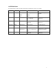
The specific ports shown above have the following Port VLAN ID settings (The Port VLAN ID settings for each port are configured in their respective Port Specific screen (in the Port Manager Menu) or in the VLAN Administration page): Port 01: 2 Port 02: 15 Port 03: 1 Port 04: 1 Port 05: 5 Port 06: 1 Port 07: 1 Port 08: 1 Port 09: 10 Port 10: 1 Port 11: 10 Port 12: 10 The following scenarios will produce results as described below: 1.
Appendix C: Features, Defaults and Specifications The IntraCore 65120 is shipped with the following factory default settings and specifications: • • • • • • • • • • • • Switching Method: Store-and-forward System Packets Buffer Size: 1.5MB MAC Address Table: 8000 Full-Duplex: Standards-based auto-negotiation enabled VLAN: 64 port-based VLANs, with IEEE 802.1Q tagging Spanning Tree Protocol: 802.1D, enabled Priority: 802.
• • • Supports up to 64 virtual LANs 17-inch and standard 1U chassis high Internal power supply 45
Appendix D: FCC Compliance and Safety Statements FCC Compliance Statement This equipment generates and uses radio frequency energy and if not installed and used properly, that is, in strict accordance with the instructions provided with the equipment, may cause interference to radio and TV communication.
Appendix E: Online Warranty Registration Before calling Asanté Technical Support, please register your switch online at www.asante.com/support/registration.html. By doing so, you’ll be entitled to special offers, up-to-date information and important product bulletins.