
Instruction Manual


Advanced Management
Page 4-40
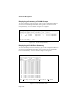
For example, assume a three-switch network that includes three VLANs;
VID 1, VID 2, and VID 3. Also assume that the switches (A, B, and C) are
configured with the VLAN groups shown in Figure 4-14. In this case, switch
A and switch C both include VLAN #2 in their VLAN groups. However, the
VLAN traffic must cross switch B.
Using GVRP, switches A and C can register their interest in VLAN #2 with
switch B. Then switch B can join the VLAN #2 topology when it receives
frames tagged with that VID. Once it does, it can then pass that VLAN
traffic to switches A and C.
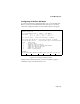
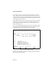
To access the GVRP Configuration Menu, type v in the Configuration Menu
to access the VLAN Management Menu, then type g to access the GVRP
Configuration Menu. A screen similar to Figure 4-15 appears.
Figure 4-15 GVRP Configuration Menu
Navigate to the VLAN that you want to configure by typing a command as
shown at the bottom of the screen.
IntraCore 8000 GVRP Configuration Menu System GVRP: Disabled
VLAN[1] Id : 1 Dynamic Port Map
Module Port List 1 8 9 16 17 24 25 32
====== ======== ======== ======== ========
1 +: Member -------- -------- -------- XXXXXXXX
2 -: Not Member -------- -------- -------- XXXXXXXX
3 --XXXXXX XXXXXXXX XXXXXXXX XXXXXXXX
4
5
6
7
8
<Cmd> <Description>
t Toggle System GVRP Status
e Enable GVRP on Group of Ports
d Disable GVRP on Group of Ports
f Forbidden Set Configuration
r Regisration Fixed Set Configuration
Command>
S
elect VLAN Next VLAN Previous VLAN Quit