FriendlyNET® FM2017 SNMP/Web Managed Switch with Fiber Option User’s Manual
Table Of Contents Chapter 1. Introduction Features Ethernet Switching Technology Management Methods Chapter 2. Hardware Installation Package Contents Front Panel Rear Panel Mounting Configurations Powering on the Switch Optional FX100 Modules Chapter 3. Network Application Small Workgroup Segment Bridge VLAN Application Chapter 4. Network Configuration Connecting a Terminal or PC to the Console Port Assigning IP Address Secured IP Chapter 5. Web-Based Management System Login Appendix A.
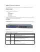
Chapter 1. Introduction Thank you for purchasing an Asanté FriendlyNET FM2017 SNMP/Web managed switch. This switch is designed to build high-performance switched networks. It uses store-and-forward technology, providing low latency for high-speed networking, and is targeted at workgroup, department or backbone computing environments at small to medium enterprise businesses. The switch features full plug-and-play installation. LED indicators provide for easy monitoring of switch operation.
Ethernet Switching Technology Ethernet switching technology has dramatically boosted the total bandwidth of a network, eliminating congestion problems inherent with Carrier Sense Multiple Access with Collision Detection (CSMA/CD) protocol, and has greatly reduced unnecessary transmissions.
Chapter 2. Hardware Installation This chapter describes the front and rear panels of the FM2017, and explains how to install, mount and apply power to the switch. Package Contents The switch is shipped with the following items: • • • • • • Switch AC power cord Four (4) Rubber feet Rack mount Kit RS-232 cable User’s Manual (this document) Compare the contents of your switch’s package against the items listed above. If any of the items is missing or damaged, contact your dealer immediately for service.
Rear Panel The rear panel contains the Network Management module and the 3-pronged power plug. The switch uses AC in the range of 100-240V AC, 50-60Hz.
• • • • FX100-MMC FX100-SMC15 FX100-SMC30 FX100-SMC60 The FX100 modules are designed to extend the allowable distance between the switch and other network devices. The maximum distance that can be achieved with fiber cabling is 2 kilometers (multi-mode fiber) and up to 15, 30 or 60 kilometers (single-mode fiber). Front Panels The front panels of the FX100 modules consist of LED indicators, two thumbscrews, a DIP-switch for half and full-duplex mode (full-duplex is the default) and one fiber port.
Chapter 3. Network Application This section provides a few samples of network topology in which the switch can be used. In general, the switch is designed to be used as a segment switch. That is, with its large address table (8000 MAC address) and high performance, it is ideal for interconnecting networking segments. You can use the switch to connect PCs, workstations, and servers to each other by connecting these devices directly to the switch.
Chapter 4. Network Configuration This chapter explains how to configure console management via a direct connection to the console port of the switch. Console management involves the administration of the switch via a direct connection to the RS-232 console port. This port is a female DB-9 connector. From the main menu of the console program, the user has access to manage the functions of the switch.
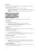
---<>---------------------------[1.0(beta 2)]---[MAC=00:00:94:D1:1C:22] [IP=192.168.0.1] [mask=255.255.255.0] [broadcast=255.255.255.255] [gateway=0.0.0.0] -----------------------------------------------------------------------1. boot-method = [flash] 2. ip-address = [192.168.0.1] 3. subnet mask = [255.255.255.0] 4. broadcast = [255.255.255.255] 5. gateway = [0.0.0.0] 6. traps=[0.0.0.0] [0.0.0.0] [0.0.0.0] [0.0.0.0] 7. get-community = [public] 8. set-community = [private] 9.
E. Http server = [on] F. Telnet/Http username = [root] G. Telnet/Http password = [enabled] H. reboot I. logout J. ping K. help L. loaddefault M. securedip = [0.0.0.0],[0.0.0.0],[0.0.0.0] >>>> Press H to reboot the switch after making your change. Press Enter twice, and the new IP address will now be displayed. By the similar methods, you can configure the Subnet Mask (Default subnet mask is 255.255.255.0), Broadcast (Default Broadcast is 255.255.255.255), and Default Gateway (Default Gateway is 0.0.0.0).
Chapter 5. Web-Based Management This section introduces the configuration and functions of the web-based management of switch. The FM2017 provides an embedded HTML website residing in the CPU module. It offers management features and allows users to manage the switch from anywhere on the network through a standard web browser. System Login 1. 2. 3. Launch your web browser. Enter the IP address of the switch in the URL window (http://192.168.0.1). Then press Enter.
Inside the System page, the following information about the switch is listed: Network Setting • • • • IP address: 192.168.0.1 Subnet Mask: 255.255.255.0 Broadcast: 255.255.255.255 Default gateway: 0.0.0.0 The configuration above is only a reference setting. If you want to reset or change the numbers, you can click Agent Config to change or reset them.
The data is automatically updated at regular intervals. Port Config Screen You can use the Port Config page to disable/enable each port. By default, all the ports are Enabled. To disable or enable a port: 1. 2. 3. Select the drop-down menu in the Status column. Choose the status you want for each Ethernet and Fiber port. Remember to click Apply button after finishing your new settings.
To set these parameters for a port: 1. 2. 3. Select the drop-down menu in Speed/Duplex column. Select one of the following choices: Auto/flow control enabled, Auto/flow control disabled, 100BaseTx/Full Duplex, 100Base-Tx/Half Duplex, 10Base-T/Full Duplex or 10Base-T/Half Duplex. Click Apply. VLAN Screen A VLAN (Virtual LAN) is a group of switch ports designated by the switch as belonging to the same broadcast domain.
Agent Config Screen In the Agent Config page, the switch’s current configurations are displayed. You can refer to the following Agent Config page for your own setting. Boot Method There are three modes of Boot Method: • • • FLASH: Boot your system by flash settings. Flash memory resides in a chip and holds its content without power. Software images can be stored, booted and rewritten as necessary BOOTP: Boot your system from BOOTP server (Bootstrap Protocol).
Default Agent Configuration The following are the default values of the Agent Config of the switch. You can change the information listed by entering new information (for example, you can change the switch’s IP address by directly typing in a new IP address). Click Apply after entering the information. • • • • • • • • • • • • • • • • • • • Boot-Method: flash IP address: 192.168.0.1 Submask: 255.255.255.0 Broadcast: 255.255.255.255 Gateway: 0.0.0.0 Trap1: 0.0.0.0 Trap2: 0.0.0.0 Trap3: 0.0.0.0 Trap4: 0.0.0.
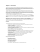
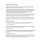
Appendix A. Troubleshooting This section is intended to help you solve the most common problems on the switch. If you still are having problems after reading through the information here, contact Asanté’s Technical Support for assistance. Your switch can easily be monitored through the LED indicators to assist in identifying problems. Below are listed common problems that you may encounter and where you can find possible solutions.
Appendix B. Internet Explorer Setting If you are using Internet Explorer, you have to modify the browser setting to enable Java applets to use network ports. We used Internet Explorer 5.0 for the following demonstration. First, select ”Internet Optional..” under “Tools” of the function bar, then follow the step-by-step instructions below. 1. 2. Select the Security tab. Click Trusted sites. 3. Click Sites. 4. Add the IP address (http://192.168.0.1) of the switch to the zone, and then click Add. 5.
6. Go back to Internet Options, then click Custom Level. 7. 8. Scroll down to find Java. Select Custom under Java and click Java Custom Settings. 9. Select the Edit Permissions tab. 10. Select Enable under Unsigned Content, and then press OK.
Appendix C. Specifications and Warranty Statement FriendlyNET FM2017 Specifications Standards Protocol Maximum Forwarding Rate LED Indicators Copper Network Cables Fiber Link Maximum Distance Interface Dimensions Operational Temperature Storage Temperature Operational Humidity External Power Supply Power Consumption EMI Safety Limited Warranty IEEE 802.3 10Base-T Ethernet IEEE 802.3u 100Base-TX Fast Ethernet ANSI/IEEE 802.
FriendlyNET FM2017 SNMP/Web Managed Switch with Fiber Option User’s Manual Asanté Technologies, Inc. 821 Fox Lane San Jose, CA 95131 USA SALES 800-662-9686 Home/Office Solutions 800-303-9121 Enterprise Solutions 408-435-8388 TECHNICAL SUPPORT 801-566-8991: Worldwide 801-303-3787: FAX www.asante.com support@asante.com Copyright 2002 Asanté Technologies, Inc. All rights reserved.