FriendlyNET® FR1104-G Cable/DSL 802.
Asanté Technologies, Inc. 821 Fox Lane San Jose, CA 95131 USA FriendlyNET FR1104-G User’s Manual, Version 1.21 TECHNICAL SUPPORT www.asante.com/support COVER: Asanté FriendlyNET FR1104-G © 2004 Asanté Technologies, Inc. All rights reserved. No part of this document, or any associated artwork, product design, or design concept may be copied or reproduced in whole or in part by any means without the express written consent of Asanté Technologies, Inc.
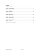
Contents Chapter 1. Introduction .................................................................................................................... 4 Chapter 2. Hardware Details ........................................................................................................... 7 Chapter 3. Configuring Router....................................................................................................... 10 Chapter 4. Main Menu .................................................................
Chapter 1. Introduction The Asanté FriendlyNET FR1104-G routers give you the freedom to share your Internet connection without wires. Megapixel photos, streaming video and everyday emails with large attachments move faster through this router. With numerous international awards and accolades, Asanté has consistently delivered world-class features in all of its products. This third-generation FriendlyNET router provides higher levels of security, reliability and performance—all at an affordable price.
Chapter 1. Introduction Home users will appreciate the on-screen configuration wizard and other integrated tools. • Upgradeable wireless antenna for greater directional range. • Compatible with dynamically configured devices, like the Microsoft Xbox game console and MSN Messenger. Application-sensing tunnels for RealPlayer, QuickTime, AOL Instant Messenger, ICQ, mIRC, Dialpad, Quake, Half-Life, Star Craft Unreal Tournament and others (user-definable).
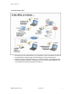
Chapter 1. Introduction 1.5 TYPICAL INSTALLATION • • Place the router in a central location of your business or home. This allows the router to provide maximum wireless range—while minimizing access by external users. Although the router supports both 802.11b (11 Mbps) and 802.11g (54 Mbps) speeds, whenever possible choose 802.11g adapters for your computers and peripherals. The router will deliver maximum performance at 802.11g.
Chapter 2. Hardware Details This chapter describes the FriendlyNET router hardware. 2.1 FRONT PANEL The FriendlyNET router provides color-coded indicators to show the status of various functions. • Reset. To restore the router to factory default settings, hold the recessed reset button for about 5 seconds. The Status LED should flash 5 times. Release the button.
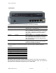
Chapter 2. Hardware Details 2.2 REAR PANEL Looking at the router from the rear, the following connectors are available. Port 5 VDC Function Power Input 1 through 4 LAN Ports Internet Internet Wireless Antenna Description Plug in the Asanté FR1104 external power module rated at 5 VDC, 1.5 A (minimum). Plug in a cable from your computer to one of these ports. 10/100BaseT Fast Ethernet (RJ-45 connector). Auto-Uplink™ supports any standard or “crossover” cable.
Chapter 2. Hardware Details 2.3 BOTTOM VIEW The bottom of the router contains three sections: • • • Holes for wall or desktop mounting (screws sold separately). Rubber feet (user-installable). Product identification label showing model number (i.e., FR1104-G), regulatory information (compliance with FCC and CE), warranty and service information and other details.
Chapter 3. Configuring Router The FriendlyNET router is configured using any standard web browser: • Internet Explorer (v5 and later). • Netscape (v5 and later). • Safari (v1 and later). The default IP address for the router is 192.168.123.254 with default subnet mask 255.255.255.0. To log in: 1. Enter the router’s default system password: admin 2. Click Log in button. 3.
Chapter 3. Configuring Router A B If the main screen still does not appear (or your password is not accepted), reset the router to factory default settings. 1. Locate the recessed Reset button on the router’s front panel [A]. 2. Depress the button using a pencil or blunt end of a paper clip. 3. Hold the recessed reset button for about 5 seconds. The Status LED [B] should flash 5 times. 4. Release the Reset button.
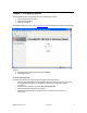
Chapter 4. Main Menu Upon successfully logging into the router, the System Status page will be displayed: A C B E D Tip: The letters A–E (above) correspond to the next five descriptions. A. This screen shows the status of the router and its connections. To return to this screen, click Status from the menu at the left. To set up this router for the first time, click Setup Wizard. Follow the on-screen instructions. See Quick Start Guide poster for details.
Chapter 4. Main Menu B. To configure the router’s more advanced features, choose from the following 5 menus. Menu Basic Setting Forwarding Rules Security Settings Advanced Setting Toolbox Functions Primary Setup: LAN IP, WAN type, renew IP forever, NAT DHCP Server: IP pool starting/ending address, fixed mapping Wireless: SSID, channel, WEP, 802.
Chapter 4. Main Menu • Domain Name Server (DNS). The Internet server used to translate names into IP addresses. The www.asante.com domain name translates to 207.176.137.22. 4.2 WAN STATISTICS These items quantify the types of traffic received (inbound from Internet) and sent (outbound to Internet) by the router. • • • Octets: Equivalent to a byte (8-bits) of information. Unicast Packets: Data sent by a single sender to a single recipient. Non-Unicast Packets: Other data sent.
Chapter 4. Main Menu Tip: This log may be emailed or automatically stored on a syslog server. See Advanced Settings > System Log.
Chapter 4. Main Menu 4.4 CLIENTS LIST A B • • Wake up. Wake-on-LAN (WoL) is a technology used to remotely power-up a network device. To use this feature, your target computers must be WoL-enabled. To wake up a device, select the device [A] and click Wake up [B]. Confirm your selection by clicking OK on the dialog box. Delete. Select client [A] and click Delete. Confirm your deletion by clicking OK on the dialog box.The entry will be deleted from this list.
Chapter 4. Main Menu 4.4 ADMINISTRATOR TIME-OUT For security reasons, the router administration will automatically terminate your session after a set period of inactivity. To set this idle time, see Security Settings > Miscellaneous > Administrator Time-Out.
Chapter 5. Setup Wizard If your router has already been configured, skip to chapter 6. Otherwise, login to the router, and configure your router using the Setup Wizard. From the menu on the left, click Setup Wizard. Click Next to proceed to the next screen.
Chapter 5. Setup Wizard 5.1 SELECT WAN TYPE Choose from these Internet (WAN) types: • • • • • Static IP Address. ISP assigns you a static IP address. Dynamic IP Address. Obtain an IP address from ISP automatically. This is the most common configuration (especially for cable modem users) and is the router’s default setting. Dynamic IP Address (Special). Select this if your ISP is Road Runner or Telstra BigPond. PPP over Ethernet. Some ISPs require the use of PPPoE to connect to their services.
Chapter 5. Setup Wizard 5.2 STATIC IP ADDRESS The following information must be provided by your ISP. If your ISP did not provide this info, you may have a dynamic IP address; choose one of the other settings: • Static IP Address. The router’s Internet (WAN) IP address. • Static Subnet Mask. Default is 255.255.255.0 • Static Gateway. The IP address for the ISP that connects this router to the Internet. To verify that your ISP is up, ping this gateway address. • Static Primary DNS.
Chapter 5. Setup Wizard 5.3 DYNAMIC IP ADDRESS In most cases, you will not need to make any changes. Click Next to proceed to the next screen. The following setting is optional. Most ISPs will not require this info. • WAN’s MAC Address. Some ISPs limit the use of routers. Click Clone MAC to have the router use the MAC address of this computer. Click Next to proceed to the next screen (“Configuration Completed”); see section 5.7.
Chapter 5. Setup Wizard 5.4 DYNAMIC IP ADDRESS (ROAD RUNNER) The following information must be provided by your ISP: • Account. Your user account name. • Password. Your account password. • Login Server. Optional. Click Next to proceed to the next screen (“Configuration Completed”); see section 5.7.
Chapter 5. Setup Wizard 5.5 PPP OVER ETHERNET (PPPOE) The following information must be provided by your ISP: • Account. Your user account name. For security reasons, this field appears blank the next time you see this screen. • Password. Your account password. For security reasons, this field appears blank the next time you see this screen. • Primary DNS. The Internet server used to translate names into IP addresses. • Secondary DNS. Optional.
Chapter 5. Setup Wizard 5.6 POINT-TO-POINT TUNNELING PROTOCOL (PPTP) The following information must be provided by your ISP: • My IP Address. The router’s Internet (WAN) IP address. • My Subnet Mask. Default is 255.255.255.0 • Server IP Address. The IP address for your ISP’s server (gateway) that connects this router to the Internet. To verify that your ISP is up, ping this gateway address. • PPTP Account. Your user account name. • PPTP Password. Your account password.
Chapter 5. Setup Wizard 5.7 CONFIGURATION COMPLETED 1. Click Reboot to restart your router. Your installation is complete. 2. To verify your installation, visit a website, like www.asante.com. If you are unable to connect to a website, then restart your computer(s).
Chapter 6. Basic Setting After using the Setup Wizard, described in the previous chapter, you may fine-tune your configuration. A B Log in to the router, click Basic Setting link [A] and choose from one of the four sub-menus [B]. Basic Setting Primary Setup DHCP Server Wireless Change Password Asanté FriendlyNET FR1104-G Functions LAN IP, WAN type, renew IP forever, NAT IP pool starting/ending address, fixed mapping SSID, channel, WEP, 802.
Chapter 6. Basic Setting 6.1 PRIMARY SETUP – DYNAMIC IP ADDRESS A C B In most cases, you will not need to make any changes. • • LAN IP Address. The router’s LAN IP address and the gateway address for computers on your network (LAN and WLAN). In most cases, do not change the default value (192.168.123.254). LAN Subnet Mask. Default is 255.255.255.0 This is a dynamic screen. To minimize confusion, only the fields used in your configuration are shown here.
Chapter 6. Basic Setting 6.2 CHOOSE WAN TYPE After clicking Change from the Basic Setting > Primary Setup screen, you will see this: A B Choose from these Internet (WAN) types: • • • • • Static IP Address. ISP assigns you a static IP address. Dynamic IP Address. Obtain an IP address from ISP automatically. This is the most common configuration and the router’s default setting. Dynamic IP Address (Special). Select this if your ISP is Road Runner or Telstra BigPond. PPP over Ethernet.
Chapter 6. Basic Setting 6.3 PRIMARY SETUP - STATIC IP ADDRESS • • • LAN IP Address. The router’s LAN IP address and the gateway address for computers on your network (LAN and WLAN). In most cases, do not change the default value (192.168.123.254). LAN Subnet Mask. Default is 255.255.255.0 WAN Type. Static IP Address. The following fields will appear when the WAN Type is Static IP Address. Other fields will appear when the WAN Type is changed.
Chapter 6. Basic Setting 6.4 PRIMARY SETUP - DYNAMIC IP ADDRESS • • • LAN IP Address. The router’s LAN IP address and the gateway address for computers on your network (LAN and WLAN). In most cases, do not change the default value (192.168.123.254). LAN Subnet Mask. Default is 255.255.255.0 WAN Type. Dynamic IP Address. The following fields will appear when the WAN Type is Dynamic IP Address. Other fields will appear when the WAN Type is changed.
Chapter 6. Basic Setting 6.5 PRIMARY SETUP - DYNAMIC IP ADDRESS (ROAD RUNNER) • • • LAN IP Address. The router’s LAN IP address and the gateway address for computers on your network (LAN and WLAN). In most cases, do not change the default value (192.168.123.254). LAN Subnet Mask. Default is 255.255.255.0 WAN Type. Dynamic IP Address. The following fields will appear when the WAN Type is Dynamic IP Address. Other fields will appear when the WAN Type is changed.
Chapter 6. Basic Setting 6.6 PRIMARY SETUP - PPP OVER ETHERNET (PPPOE) A • • LAN IP Address. The router’s LAN IP address and the gateway address for computers on your network (LAN and WLAN). In most cases, do not change the default value (192.168.123.254). WAN Type. PPP over Ethernet. The following fields will appear when the WAN Type is PPP over Ethernet. Other fields will appear when the WAN Type is changed. The following information must be provided by your ISP. • • • • • • PPPoE Account.
Chapter 6. Basic Setting 6.7 PRIMARY SETUP - POINT-TO-POINT TUNNELING PROTOCOL (PPTP) • • LAN IP Address. The router’s LAN IP address and the gateway address for computers on your network (LAN and WLAN). In most cases, do not change the default value (192.168.123.254). WAN Type. PPTP. The following fields will appear when the WAN Type is PPTP. Other fields will appear when the WAN Type is changed. The following information must be provided by your ISP. • • • • • • • My IP Address.
Chapter 6. Basic Setting 6.8 PRIMARY SETUP - VIRTUAL COMPUTERS From the Primary Setup screen, click Virtual Computers. Some business-class Internet service plans provide multiple static IP addresses. If you subscribe to such a service, you can use the router’s firewall and other features to protect the computers behind the router. Virtual Computer maps one external (WAN, Internet) IP Address to one local (LAN, WLAN) IP address. If you only have 1 static IP address, do not enter it into this table.
Chapter 6. Basic Setting 6.9 DHCP SERVER From the Basic Settings menu, click DHCP Server. All computers and devices connected to the router need to be configured. Since TCP/IP configuration can be tedious, the router’s dynamic host configuration protocol (DHCP) service can automatically configure each computer set for “Obtain an IP address automatically.” Tip: To check if your computer can accept the router’s DHCP settings, see your computer’s network properties.
Chapter 6. Basic Setting The DHCP Server settings can be set as follows: • DHCP Server. Default is Enable (recommended). • Lease Time. Do not change this field (recommended). • IP Pool Starting Address. Default is 100 (recommended), minimum value is 1. This field controls the last octet of your network (LAN and WLAN) IP address range. By default, the router uses 192.168.123.100 through 192.168.123.199 • IP Pool Ending Address: 199. Maximum value is 253 (if the router is set for 192.168.123.254).
Chapter 6. Basic Setting 6.10 CLIENTS LIST A B • • Wake up. Wake-on-LAN (WoL) is a technology used to remotely power up a network device. To use this feature, your target computers must be WoL-enabled. To wake up a device, select the device [A] and click Wake up [B]. Confirm your selection by clicking OK on the dialog box. Delete. Select client [A] and click Delete. Confirm your deletion by clicking OK on the dialog box. The entry will be deleted from this list.
Chapter 6. Basic Setting 6.11 FIXED MAPPING AND MAC ADDRESS CONTROL B A C D On this screen, you can manually associate specific local (LAN or WLAN) IP addresses with a specific computer or device (client). • • • MAC Address Control. Click Enable to allow the settings on this page to become effective. Connection Control. Enable this rule to allow wired (LAN) and wireless (WLAN) clients to have controlled access.
Chapter 6. Basic Setting For medium security, grant access to all wired clients, but only specific wireless clients: • Mac Address Control: Enable. • Connection Control: Enable. Allow unspecified MAC addresses to connect. • Association Control. Enable. Deny unspecified MAC addresses to associate. • Control Table. Use the DHCP clients drop-down menu to add each wireless client to the list. Check A (associate control) for each client. • When finished, click Save.
Chapter 6. Basic Setting 6.12 WIRELESS SETTING This screen establishes the settings for the wireless network (WLAN). You must match these settings with all wireless clients that will use this router. • • Network ID (SSID or ESSID). Default is default. If you have multiple wireless access points with routers (like the FR1104-G), clients can freely roam between them without making any changes. Every wireless client using the SSID defined here will have access to the router.
Chapter 6. Basic Setting • Security. Choose the appropriate security level for your network. Security None WEP 802.
Chapter 6. Basic Setting SECURITY: WEP A B • • WEP. Choose the encryption standard. The 128-bit design is more secure than 64-bit and the 256-bit is much more secure than 128-bit. However, not all wireless adapters support 256-bit WEP encryption. WEP Key 1, 2, 3, 4. Select one field and enter a random hexadecimal key for your selected WEP security level. A hexadecimal key uses one of these digits: 0, 1, 2, 3, 4, 5, 6, 7, 8, 9, A, B, C, D, E or F.
Chapter 6. Basic Setting SECURITY: 802.1X A B To use this security feature, you must have an 802.1X-compatible authentication server. Use the settings provided by your remote authentication dial-in user service (RADIUS) server. Authentications using PEAP-CHAPv2 and PEAP-TLS are supported. • • • • Encryption Key Length. Choose 64 or 128 bits. RADIUS Server IP. Enter the server’s IP address. RADIUS Port. Enter the authentication tcp/udp service port number. Default is 1812 (per RFC 2026).
Chapter 6. Basic Setting SECURITY: WPA-PSK A B In a home or small business network, Wi-Fi protected Access (WPA) uses a special mode called WPA-PSK. The PSK refers to a pre-shared key (or password) used to initialize authentication. This is the most common method of implementing WPA wireless security in homes and small businesses. For larger businesses and organizations with an 802.1X RADIUS authentication server, choose WPA mode (not WPA-PSK).
Chapter 6. Basic Setting SECURITY: WPA A B For businesses and larger organizations with an 802.1X RADIUS authentication server, choose this Wi-Fi protected Access (WPA) mode—not WPA-PSK. The PSK refers to a pre-shared key (or password) used to initialize authentication. This is the most common method of implementing WPA wireless security. For businesses and organizations with an 802.1X RADIUS authentication server, choose WPA mode (not WPA-PSK). • • • RADIUS Server IP. Enter the server’s IP address.
Chapter 6. Basic Setting 6.13 WPA FOR WIRELESS CLIENTS In most cases, you will need to upgrade and install your wireless client utility software and drivers before using WPA. Check with your wireless adapter manufacturer for utility software and driver updates as necessary. Follow their specific instructions to configure your wireless client for WPA. Asanté supports WPA on these FriendlyNET wireless adapters: • AeroLAN AL5410-G Wireless: 802.11g WPA: No • AeroLAN AL5403-XG Wireless: 802.
Chapter 6. Basic Setting APPLE MACINTOSH OS X Asanté’s FriendlyNET AeroLAN AL5402-XG, AL5403-XG and Apple’s AirPort Extreme cards support WPA when using the current Apple AirPort driver in OS X 10.2.8 and above; earlier versions of Mac OS X and OS 9 are not supported by Apple. Using the Apple AirPort wireless configuration utility in Mac OS X, you can enable WPA support to work with the Asanté FR1104-G router using WPA mode. Note: WEP and WPA are mutually exclusive; they can’t be used simultaneously.
Chapter 6. Basic Setting 6.14 CHANGE PASSWORD The router’s administrator’s default password is admin. Caution! You should change the password immediately and write down the new password in a safe place. • • • Old password. Factory default is admin. New password. Choose your own password. For improved security, avoid using names and words that can be found in a dictionary. Reconfirm. Re-type your new password.
Chapter 7. Forwarding Rules After logging into the router, click on the Forwarding Rules link [A]. Choose from one of the three sub-menus [B]. A B This chapter describes how to customize the router’s forwarding rules so you may run specialized servers and applications on your local network. In most cases, you will never need to make any changes in this section.
Chapter 7. Forwarding Rules 7.1 VIRTUAL SERVER By default, the router’s network address translation (NAT) firewall will block unrecognized incoming packets from the Internet (WAN) to protect internal clients on the LAN and WLAN. To allow direct external access for specific Internet services, use the Virtual Server capability. For example, if you have FTP, web and VPN servers on your local network, you could define them as follows: Server FTP Web VPN ID 1 2 3 Service Port 21 80 1723 Server IP 192.168.
Chapter 7. Forwarding Rules Popular Internet Services Web Telnet SMTP POP3 FTP ISAKMP DNS Authentication PPTP Service Port 80 23 25 110 21 500 53 113 1723 Comment HTTP Email Email After making changes, be sure to click Save. To restore the last saved settings, click Undo. To read on-screen information on this page, click Help.
Chapter 7. Forwarding Rules 7.2 SPECIAL APPLICATIONS AND GAMES A B C Some applications and Internet games utilize a range of service ports that are normally blocked by the router’s network address translation (NAT) firewall. This Special Applications feature lets you enable pre-defined applications and your own custom settings. Each Special Application setting can only be used by one client at a time. Your applications provider will be able to provide these settings for you. • • Trigger.
Chapter 7. Forwarding Rules 7.3 MISCELLANEOUS This page defines two special services: DMZ (demilitarized zone) for unrestricted two-way communications and non-standard FTP port. • • • IP Address of DMZ host. If your special application or Internet game does not work with the Special Applications settings, you can logically place it “in front” of the router’s NAT firewall. Since this exposes the computer to unauthorized users from the Internet, this feature should only be activated when necessary.
Chapter 8. Security Setting After logging into the router, click on the Security Setting link [A]. Choose from one of the five sub-menus [B]. A B This chapter lets you tailor the router’s extensive security features to best protect your local network. The router uses a “double firewall” (NAT with PF/DF) to provide secure data communications.
Chapter 8. Security Setting 8.1 PACKET FILTERS – OUTBOUND FILTER Packet filters allow you to control access to the network (local and Internet) by analyzing every inbound and outbound packet. Depending upon the rule you define, packets will be evaluated against source address, destination address, service port and time of day/week. Since inbound packets are naturally filtered by the router’s NAT firewall, the inbound filters only protect the Virtual Servers and DMZ host.
Chapter 8. Security Setting • • Enable. You may selectively enable or disable each rule. Use Rule #. Use the drop-down menu at the bottom of the screen to quickly fill in a scheduling rule. Tip: Rules are scheduled in Advanced Settings > Schedule Rule. After making changes, be sure to click Save. To restore the last saved settings, click Undo. To assign filters for inbound traffic, click Inbound Filter. (See 8.
Chapter 8. Security Setting 8.2 PACKET FILTERS – INBOUND PACKET FILTER After making changes, be sure to click Save. To restore the last saved settings, click Undo. To assign filters for outbound traffic, click Outbound Filter. To set MAC address controls for specific clients, click MAC Level. To read on-screen information on this page, click Help.
Chapter 8. Security Setting 8.3 MAC ADDRESS CONTROL From the Inbound (or Outbound) Packet Filter screen, click MAC Level. B A C D On this screen, you can manually associate specific local (LAN or WLAN) IP addresses with a specific computer or device (client). • • • MAC Address Control. Click enable to allow the settings on this page to become effective. Connection Control. Enable this rule to allow wired (LAN) and wireless (WLAN) clients to have controlled access.
Chapter 8. Security Setting • • Control Table. Use the DHCP clients drop-down menu to add each client to the list. Check both C (connection control) and A (association control) for each client. When finished, click Save. Tip: For maximum security, see the Security Settings menu.
Chapter 8. Security Setting 8.4 DOMAIN FILTER • • • • • • Domain Filter. Check to prevent clients from accessing specific websites (URLs). Log DNS Query. Check to log all domain name requests. For example, a user attempting to browse www.google.com from his browser will have www.google.com entered into the log. See Status > View Log to see the on-screen log. Privileged IP Addresses Range. Exclude clients from the restrictions on this page. Domain Suffix. Exclude access to sites with this suffix.
Chapter 8. Security Setting 8.5 URL BLOCKING By enabling this function, any website with the specified keyword(s) will be blocked and access attempts will be logged. See Status > View Log to view the on-screen log. • • • URL Blocking. Check to block clients from accessing websites with the specified keyword in its URL. URL. Enter the keywords of the websites you want to block. Enable. Individual rules may be enabled and disabled. Sample 1 URL Keywords sex Enable 9 2 .tv 9 Websites Blocked www.sex.
Chapter 8. Security Setting 8.6 MISCELLANEOUS SECURITY SETTINGS This configuration page allows you to limit the vulnerabilities of your router from Internet attackers. When in doubt, do not change these default settings. • Remote Administrator Host/Port. Changing this setting allows others to easily change the settings of this router via Internet. If you have a very trusted individual who can assist you with administering this router, then enable this feature only when you need assistance.
Chapter 8. Security Setting For maximum network security, Asanté recommends these settings: Miscellaneous Security Remote Administrator Host/Port Administrator Time-out Discard PING from WAN side Secure Packet Inspection (SPI) Mode Denial of Service (DoS) Attack Detection VPN PPTP/IPSec Pass-Through Setting 300 Enable No 9 9 9 9 No After making changes, be sure to click Save. To restore the last saved settings, click Undo. To read on-screen information on this page, click Help.
Chapter 9. Advanced Setting After logging into the router, click on the Advanced Setting link [A]. Choose from one of the five sub-menus [B]. A B Use the settings described in this chapter to configure the router’s advanced features. For most network installations, these settings are set only once or rarely. With only minor exceptions, you must have a strong working knowledge of routers and TCP/IP before making changes to the settings described here.
Chapter 9. Advanced Setting 9.1 SYSTEM TIME If this is the first time setting up the router, you will need to set the router’s internal clock. • Get Date and Time by NTP Protocol. Use the time provided by specified network time protocol (NTP) server. If enabled, then the router’s real-time clock (time) will be set by the specified time server (typically, once a week). If your router is not continuously connected to the Internet, click Sync Now! Choose your local time zone from the drop-down menu.
Chapter 9. Advanced Setting 9.2 SYSTEM LOG The router’s system log records specified system events plus potential security threats based upon the settings in Security Setting. The log is normally saved in volatile memory. It can be manually or automatically exported to other servers or devices. • • • • • • • • • IP Address of Syslog Server. IP address of destination syslog server. Check to enable this function. Email Alert. Click to immediately email the system log to the specified address.
Chapter 9. Advanced Setting 9.3 DYNAMIC DNS Unless your ISP has provided a static (fixed) IP address, it would be very difficult to host a local web server without this router’s Dynamic DNS (DDNS) service. By subscribing to a DDNS, whenever your Internet IP address changes, the router will automatically communicate the new IP address to the DDNS. • • • • • DDNS. Click to enable this service. Provider. Choose your DDNS service provider. Host Name. Supplied by your DDNS provider.
Chapter 9. Advanced Setting 9.4 DDNS SERVICES Since DDNS is a service offered by a third-party, Asanté Technologies does not endorse nor can Asanté be responsible or provide technical support for such services. You will need to open an account with a supported DDNS before enabling this feature. Note: For business-critical websites, a dedicated web host with a static IP address is strongly recommended. Service DynDNS.org TZO.com dhs.
Chapter 9. Advanced Setting 9.5 SNMP Simple Network Management Protocol (SNMP) is a standard for providing remote network management services via polling (get) and setting (set) device values. • • • • • Enable SNMP. The router will respond to SNMP requests from Local (LAN or WLAN), Remote (Internet) or both. Unless you must have remote SNMP support, you should only enable support for Local clients. Get Community. Define the community the router will support for GetRequest. Set Community.
Chapter 9. Advanced Setting 9.6 ROUTING The router supports dynamic and static routing for large networks with multiple routers and subnets. If you have fewer than 255 clients (computers and devices) on the same network, skip this section. Routing tables permit you to choose the physical interface address for determining outgoing IP packets.
Chapter 9. Advanced Setting 9.7 SCHEDULE RULE Services and filters can be individually turned on and off per schedule. For example, you can define these rules to control activities: • • • • Limit all outbound packets, except FTP, during OffPeak hours. Drop all packets to banned domains (espn, napster) during BusinessHours, except select managers. Log all requests to specific domains (headquarters.com) during EarlyAM. During AfterHours, block access to websites with specific keywords (sex, tv).
Chapter 9. Advanced Setting 9.8 SCHEDULE RULE SETTING From the Schedule Rule screen, click Add New Rule. A B C To define a schedule rule: A. Name your rule. B. Enter the starting and ending times for each day of the week (or every day). Be sure to use “military time” in which 08:00 is 8am and 20:00 is 8pm. C. When you’re finished, click Save.
Chapter 10. Toolbox After logging into the router, click on the Toolbox link [A]. Choose from one of the six sub-menus [B]. A B This section provides quick access to some important tools, plus specialty functions that will be valuable to only a few network administrators. Toolbox View Log Firmware Upgrade Backup Setting Reset to Default Reboot Miscellaneous Asanté FriendlyNET FR1104-G Description View system log. Download and then update the router’s internal software.
Chapter 10. Toolbox 10.1 SYSTEM LOG Click on View Log to display the System Log screen. After the log information is displayed on the screen, click Refresh to update with the latest activities. To save the log into a text file, click Download. To reset the log, click Clear. To return to the previous menu, click Back. Tip: This log may be emailed or automatically stored on a syslog server. See Advanced Settings > System Log.
Chapter 10. Toolbox 10.2 FIRMWARE UPGRADE To check for the latest firmware updates for the router, open a new web browser window and visit http://www.asante.com/support/downProd.aspx?id=FR1104-G Version G1.1 firmware is available for Mac OS (.bin) and Windows (.zip) users. Other than the compression format, the firmware for both operating systems is the same.
Chapter 10. Toolbox Firmware Update Precautions These safeguards ensure that the upgrades will be performed successfully. Tip: If your router is already functioning properly, Asanté does not recommend upgrading firmware just to have newer firmware. • • • • • • Download the FriendlyNET FR1104-G firmware from Asanté’s website (above). Back up your current firmware and settings. See Toolbox > Backup Settings. Write down your password and any special Internet settings on a separate piece of paper.
Chapter 10. Toolbox 10.3 BACKUP SETTING Click OK to save your router’s firmware and all settings into a config.bin file. You will be prompted for the name and location of the file. 10.4 RESET TO DEFAULT Click OK to restore your router’s settings to the original factory defaults: • Default IP address: 192.168.123.
Chapter 10. Toolbox 10.5 REBOOT Click OK to restart your router. This is similar to powering your router off and then on. All your saved settings will be restored.
Chapter 10. Toolbox 10.6 TOOLBOX MISCELLANEOUS • MAC Address for Wake-on-LAN (WoL). This technology is used to power up a client from another location on the local network. To use this feature, your target clients must be WoL-enabled. Enter the MAC address for the client and click Wake up. Tip: See Status > Clients List to wake up clients by name. • Domain Name or IP address for Ping Test.
Appendix A. Product Specifications Overview LAN: Wireless: Internet: Status Indicators: Wireless Antenna: Software Setup: Administration: Remote Administration: Firmware: Device Status: Supported WAN Types: Virtual Private Network: Dynamic DNS: Routing: Advanced Features: Network Security Settings Log: Firewall: MAC Address Control: Miscellaneous: Asanté FriendlyNET FR1104-G 4 x 10/100 Mbps Fast Ethernet with Auto-Uplink (100BaseTX, 10BaseT): RJ-45 connector 54 Mbps (IEEE 802.11g), 22 Mbps (TI 802.
Appendix A. Product Specifications Wireless Settings Basic: Advanced: Authentication: Frequency: Channels: Modulation Techniques: Typical Coverage: Performance Microprocessor: Internet: LAN: System Requirements Microsoft: Apple: Network Interface: Web Browser: Applications Interoperability Microsoft: Apple: Messaging: Application Tunnels: Others: Standards Compliance: Network: Network ID (SSID), channel, 64- and 128-bit WEP encryption 256-bit WEP encryption.
Appendix A. Product Specifications Support Technical Support: Product Warranty: Product Updates: Packing List Product: Localized Power: Cable: Documentation: CD-ROM: Recommended Accessories 802.11g Wireless Adapters: 802.11b Wireless Adapters: 24-hour support via web and ftp. 2-year email and telephone support 2-year product warranty covers defects in manufacturing and workmanship Free download of maintenance releases from www.asante.com website FR1104-G router 5 VDC, 2.
Asanté FriendlyNET FR1104-G User’s Manual 83