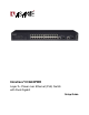
IntraCore® IC3624PWR Layer 2+ Power over Ethernet (PoE) Switch with Dual Gigabit Setup Guide
IntraCore® IC3624PWR Layer 2+ Power over Ethernet (PoE) Switch with Dual Gigabit Setup Guide Asanté Technologies, Inc. 2223 Old Oakland Road San Jose, CA 95131 USA SALES 800-662-9686 Home/Office Solutions 800-303-9121 Enterprise Solutions 408-435-8388 TECHNICAL SUPPORT 801-566-8991: Worldwide 801-566-3787: Fax www.asante.com/support support@asante.com [Default IP Address: 192.168.0.1] [Default username: root [Default password: Asante ] ] Copyright © 2004 Asanté Technologies, Inc.
Quick Start Guide Follow these steps to install your IntraCore IC3624PWR Layer 2+ Power Over Ethernet with Dual Gigabit switch. (Refer to Chapter 3 in this document or the User’s Manual for this product for complete instructions.) 1. Open the box and check the contents. 2. Install the switch in an equipment rack, or prepare it for desktop placement. 3. Connect the power supply. 4. Connect required devices to the switch. 5. Configure the switch.
Table of Contents Quick Start Guide...........................................................................................................................................................3 Table of Contents...........................................................................................................................................................4 Chapter 1: Introduction......................................................................................................................
3.7 Applying Power ..................................................................................................................................................14 3.8 Ethernet Cabling.................................................................................................................................................14 3.9 Connecting to the Console Port..........................................................................................................................15 3.9.
6.7 Run CLI ..............................................................................................................................................................23 Appendix A: Basic Troubleshooting .............................................................................................................................24 A.1 Diagnosing Switch Indicators .............................................................................................................................24 A.
Chapter 1: Introduction The IntraCore IC3624PWR Layer 2+ Power over Ethernet (PoE) with Dual Gigabit (IC3624PWR) is a product you can use to build your next generation network. The IC3624PWR device uses Layer 2+ technology and has 24 ports for 10/100/1000BastTX Fast Ethernet with 2 combination ports for added 10/100BaseT Gigabit Ethernet. Use the advanced features on the IC3624PWR switch to deploy Voice over IP (VoIP) telephones, cameras and wireless access points.
1.1.3 Management • Web browser • Telnet (multiple sessions) • Console • SNMP v1 and v2c • RMON Groups 1, 2, 3 and 9 1.2 Network Management Options The IntraCore IC3624PWR provides both local and remote management. You can configure or monitor the switch using the embedded management software or by using SNMP applications. You can manage the switch by a direct connection to the RS-232 console port (out-of-band), or a network connection (in-band) using Telnet, or the on-board Web agent. 1.
Chapter 2: Network Planning This chapter gives an overview of switch management, including the methods you can use to manage your IntraCore IC3624PWR Managed Switch. Topics include: • Management Access Overview • SNMP Access • Protocols 2.
Chapter 3: Hardware Installation and Setup This chapter describes the procedures for rack-mounting, connecting the cables, and powering up the IntraCore IC3624PWR PoE switch at your site. 3.1 Installation Overview 1. Follow these steps to install the IntraCore IC3624PWR PoE switch: 2. Open the box and check the contents. For a complete list of the items included with the switch see “Equipment Checklist” section later in this chapter. 3.
3.3 Site Requirements Consider the following site requirements for proper installation. 3.3.1 Environmental Requirements Choose a clean, dry, dust-free area location. Avoid direct sunlight, heat sources, or areas with high levels of electromagnetic interference. Failure to observe these limits may cause damage to the switch and may void the warranty. 3.3.
3.4 Preparing for Installation Switches can be mounted in a standard 19-inch equipment rack or on a flat surface. Follow these general precautions when planning your equipment locations and connections. The site needs the following: • Centrally located to the devices you want to link • Near a power outlet.
• Antistatic mat or foam 3.6 Installing the Switch The switch can be mounted in a standard 19-inch equipment rack or place on a desktop or shelf. Mounting instructions for each type of site follow. 3.6.1 Mounting the Switch in a Rack When installing this unit in an empty rack, mount it at the bottom. When mounting this unit in a partially filled rack, load the rack from the bottom to the top with the heaviest component at the bottom.
1. Attach the four adhesive feet to the bottom of the switch. 2. Set the device on a flat surface near an AC power source, making sure there are at least two inches of space on all sides for proper airflow. 3. Place each device squarely on top of the one below, in any order. When installation is complete refer to the “Applying Power” section. 3.7 Applying Power The system’s front panel LED display allows you to monitor the status of the switch. Follow these steps to connect the switch. 1.
When attaching a workstation to the switch, a standard straight-through CAT5 cable may be used. 3.9 Connecting to the Console Port The DB-9 serial port located on the front panel is used to connect to the switch for out-of-band console configuration. The on-board configuration program can be accessed from a terminal or a PC running a terminal emulation program. The pin assignments used to connect to the serial port are provided in the following tables. 3.9.
Chapter 4: Connecting Network Devices The switch is designed to interconnect multiple segments (or collision domains). It can be connected to network cards in PCs and servers, and to hubs, routers, or other switches. 4.1 Twisted-Pair Devices Each device requires an unshielded twisted-pair (UTP) cable with RJ-45 connectors at both ends. Use Category 5 for 100BaseTX connections, and Category 3, 4 or 5 for 10BaseT connections.
Chapter 5: Configuring the Switch This chapter takes you through the steps required to initially connect the switch to a console, set up initial passwords, configure an IP address, and restore factory defaults. For complete information about configuring, monitoring, and maintaining your switch, refer to the System Management Guide. 5.1 Connecting to the Switch The switch includes a built-in network management agent.
5.2 Direct Access Direct access to the switch console is achieved by connecting the null-modem cable to the switch’s console port to a VT-100 or compatible terminal or to a PC, Apple Macintosh, or UNIX workstation equipped with a terminal-emulation program. The following list provides examples of terminal-emulation programs: • HyperTerminal (which is built into the Microsoft Windows operating systems) • ZTerm (Apple Macintosh) • TIP (UNIX workstation) Follow these steps to set up the connection.
Connection Settings The port settings are as follows: Baud Rate: 9600 Data Bits: 8 Parity: None Stop Bits: 1 Flow Control: None 1. Enter the settings. 2. Click OK. 5.3 Initial Logon The switch offers a Command Menu Interface (CMI), which is a menu-driven method for managing the switch, as well as a Command Line Interface (CLI), which uses text input to manage the switch. Unless otherwise noted, the screen examples in this chapter are from the CLI.
To use the arrow keys when attached to the User Interface using a Telnet Session, under the terminal pull down menu choose Properties and activate the VT100 Arrows option.
Chapter 6: Using the Interface The main menu displays available sub-menus. The letter within square bracket of each menu option can be typed to directly choose that option. From the main menu there are seven menu items to choose from: • General Information • Basic Configuration • Advanced Switch Configuration • Statistics • Switch Tools Configuration • Save Configuration • Run CLI To logout of the user interface, press the Ctrl and D keys at anytime during your telnet session.
• Administration Configuration • IP Configuration • SNMP Configuration • Port Configuration • System Security • Forwarding DB • SNTP Configuration • ARP Table • Quit to previous menu 6.3 Advanced Switch Configuration The Advanced Switch Configuration screen allows you to configure several advanced system-related settings. There are 10 submenus on the Advanced Switch Configuration screen.
6.6 Save Configuration Use this submenu to save the changed settings to the Flash memory after making any changes to the screens within the console interface. To save the configuration to Flash memory select Save Configuration and then press either ‘Enter’ or ‘Y’. 6.7 Run CLI Use this submenu to configure the switch using the command line interface (CLI). To return to the menu-driven interface type “exit”.
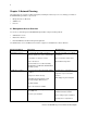
Appendix A: Basic Troubleshooting In the event the switch does not operate properly, follow the troubleshooting tips below. F you need more help contact Asante technical support at www.asante.com/support. A.1 Diagnosing Switch Indicators Refer to the following troubleshooting chart for information about the diagnostic LEDs. Problem Possible Solutions The Power LED is not lit. LED will turn off during system initialization. Check the power connection.
Appendix B: Specifications The sections below list the features and product specifications for the IntraCore IC3624PWR PoE switch. Refer to the IntraCore IC3624PWR Layer 2+ Power Over Ethernet with Dual Gigabit User’s Manual for a complete list of specification.
Appendix C: Cables and Pin Assignments This Appendix describes the information on 10BaseT/100BaseTX, 1000BaseT, and testing for existing Category 5 cables. C.1 Twisted-Pair Cable and Pin Assignments For 10BaseT/100BaseTX connections, a twisted-pair cable must have two pairs of wires. Each wire pair is identified by two different colors. For example, one green wire and another green with white stripes. You must attach an RJ-45 connector to both ends of the cable.
Pin Signal Name X Signal Name 1 Transmit Data plus (TD+) Receive Data plus (RD+) 2 Transmit Data minus (TD-) Receive Data minus (RD-) 3 Receive Data plus (RD+) Transmit Data plus (TD+) 6 Receive Data minus (RD-) Transmit Data minus (TD-) 4, 5, 7, 8 N/A N/A Note: The “+” and “-” signs represent the polarity of the wires that make up each wire pair. C.1.
EIA/TIA 568B RJ-45 Wiring Standard 10/100BASE-TX Crossover Cable White/Orange Stripe Orange End A 1 2 3 4 5 6 7 8 White/Green Stripe 1 2 3 4 5 6 7 8 Green End B C.2 Pin Assignments for 1000BaseT Pin All 1000BaseT ports support automatic MDI/MDI-X operation, so you can use straight-through cables for all network connections to PCs or servers, or to other switches or hubs. The table below shows the 1000BaseT MDI and MDI-X port pinouts. These ports require that all four pairs of wires be connected.
C.3.1 Adjusting Existing Category 5 Cabling to Run 1000BaseT If your existing Category 5 installation does not meet one of the test parameters for 1000BaseT, follow these measures to correct the problem: Replace any Category 5 patch cables with high-performance Category 5e or Category 6 cables. Reduce the number of connectors used in the link. Reconnect some of the connectors in the link. C.
Appendix D: FCC Compliance and Warranty Statements D.1 FCC Compliance Statement This equipment has been tested and found to comply with the limits for a Class A digital device, pursuant to part 15 of the FCC Rules. These limits are designed to provide reasonable protection against harmful interference when the equipment is operated in a commercial environment.
D.3 IntraCore Warranty Statement Products: IntraCore IC3624PWR Duration: 3 years Advanced Warranty Replacement: United States: Second Business Day Other Countries: See your local distributor or reseller. Asante Technologies warrants (to the original end-user purchaser) the covered IntraCore products against defects in materials and workmanship for the period specified above.
Appendix E. Online Warranty Registration Please register the switch online at www.asante.com/support/warranty/index.html. By doing so, you’ll be entitled to special offers, up-to-date information, and important product bulletins.