IntraCore® 35516 Series Layer 2/3/4 Gigabit Switches Setup Guide
Setup Guide
Table of Contents 1. Introduction 1.1 Features 1.2 Package Contents 1.3 LEDs 1.4 Front and Back Panel Descriptions 1.5 Management and Configuration 2. Installation and Setup 2.1 Safety Overview 2.2 Recommended Installation Tools 2.3 Power Requirements 2.4 Environmental Requirements 2.5 Cooling and Airflow 2.6 Installation Overview 2.7 Chassis Installation/Placement 2.8 Installing GBIC Interfaces 2.9 Installing Optional Emergency Power Supply 2.10 Connecting Power 2.11 Connecting to the Network 2.
Setup Guide
1 Introduction Thank you for purchasing the Asanté IntraCore 35516 Series Gigabit switch. The IC35516 is from a family of multi-media and multiprotocol switches capable of supporting Layer 2 switching and Layer 3 and Layer 4 protocols. They are designed to offer industryleading performance at a very competitive cost of ownership. Each IntraCore 35516 switch is a 16-port solution for Gigabit Ethernet switching using shared-memory architecture to achieve Gigabit switching on all ports.
1.1 Features The IC35516 is a high-performance, compact switch that is also a multi-media, multi-protocol (Ethernet, L2/L3/L4) router. The following is a partial list of the switch’s features (please refer to the User’s Manual on the CD-ROM for a complete list of features): • • • • • • • Supports SNMP and RMON Advanced VLSI switch engine IEEE 802.1Q VLAN and 802.
1.3 LEDs The system’s front panel LED display allows the manager to monitor the status of the switch. Refer to the following sections for LED information specific to the switch’s model. 1.3.1 IC35516-T The IC35516-T has one power LED indicator, one (optional) emergency power LED, and two LED indicators for each of the 16 ports. See the table below for a complete LED description. LED Color Description Power Green Power is on. Off Power is off, or main power has failed.
LED Color Description Power Green Power is on. Off Power is off, or main power supply has failed. Green Primary power has failed and optional power supply is powering the switch. Optional power supply is in standby mode and primary power is working. Emergency Power Off BaseT 10/100/1000 Link/Speed BaseT 10/100/1000 Duplex/Activity GBIC Link Green A valid 1000 Mbps link has been established. Yellow A valid 10/100 Mbps link has been established. Off No link has been established.
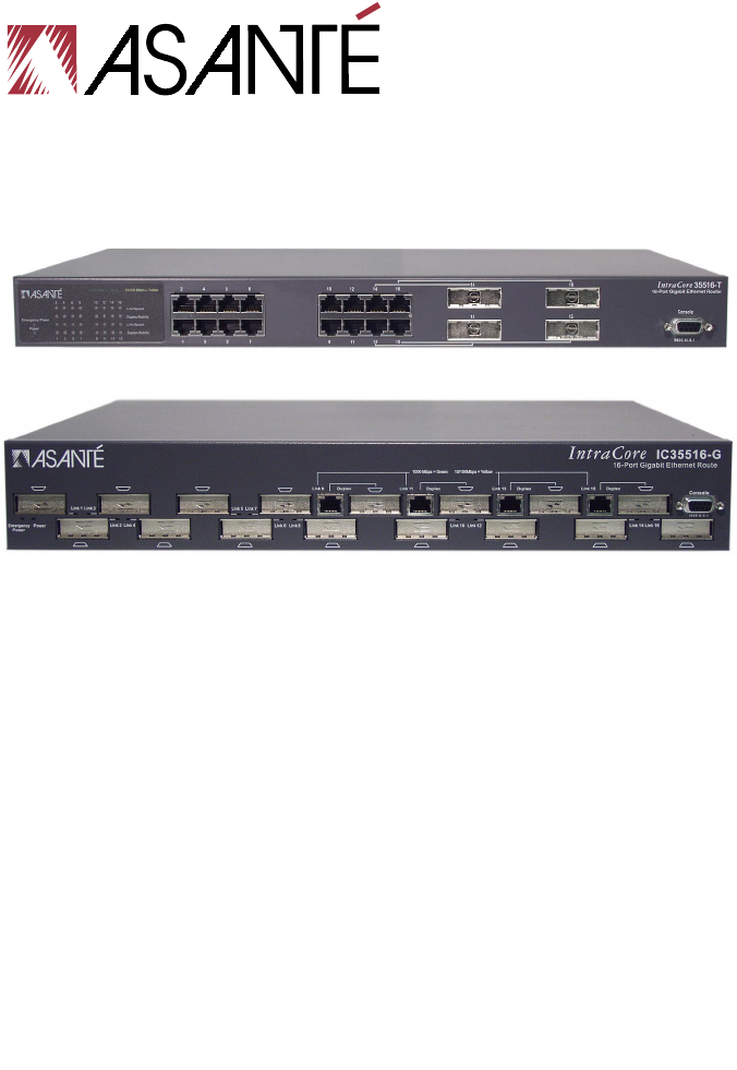
IC35516-T Front Panel The back panel, shown below, contains a 12 VDC jack for (optional) emergency power; the primary power bay cover plate; the primary power outlet; and the on/off switch. IC35516-T Back Panel 1.4.2 IC3516-G The front panel of the IC35516-G contains the following: power and port LEDs; 12 GBIC ports; 4 dual-function Gigabit ports that support either 1000BaseT or GBIC-style Gigabit Ethernet ports; and a console port.
1.5 Management and Configuration The switch is managed using Command Line Interface (CLI) in order to access several different command modes. Each command mode provides a group of related commands. Refer to the User’s Manual on the accompanying CD-ROM for more information. Console Interface Support for local, out-of-band management is delivered through a terminal or modem attached to the EIA/TIA-232 interface.
2 Installation and Setup This chapter explains how to install and connect the switch to the network. To configure the switch for management, refer to the User’s Manual on the CD-ROM. The following guidelines will help in installing the switch in such a way that it has the proper power supply and environment. 2.1 Safety Overview The following information provides safety guidelines to ensure safety and to protect the switch from damage.
• • Do not tamper with the internal components of the switch. This could void the product’s warranty Examine the work area for potential hazards (such as wet floors or ungrounded cables) and eliminate them before installing the switch For more safety information, please refer to the User’s Manual. 2.2 Recommended Installation Tools The following tools and equipment (not included) are needed to install the switch: • • • Flat head screwdriver Phillips head screwdriver Antistatic mat or foam 2.
Failure to observe these limits may cause damage to the switch and void the warranty. Avoid direct sunlight, heat sources, or areas with high levels of electromagnetic interference. 2.5 Cooling and Airflow The switch uses internal fans for air cooling. Do not restrict air flow by covering or obstructing air vents on the sides of the switch. 2.6 Installation Overview Follow these steps to install the switch: 1. 2. 3. 4. 5. Open the box and check the contents. See Chapter 1.
To mount the switch onto an equipment rack: 1. 2. 3. 4. 5. 6. Place the switch on a flat, stable surface. Locate a rack-mounting bracket (supplied) and place it over the mounting holes on one side of the unit. Use the screws (supplied) to secure the bracket (with a Phillips screwdriver). Repeat the two previous steps on the other side of the unit. Place the switch in the equipment rack. Secure the switch by securing its mounting brackets onto the equipment rack.
2.8 Installing GBIC Interfaces Instructions for installing, removing, and maintaining GBIC interfaces are provided in this section. Note: Auto-negotiation must be disabled on a port where a copper GBIC is installed. Important! The GBIC ports on the 35516-G are paired— port numbers 1/2, 3/4, 5/6, 7/8, 9/11, 10/12, 13/15, and 14/16. DO NOT use more than one copper GBIC module per pair (maximum 8 modules). 2.8.1 Installing a GBIC Note: GBICs are hot-swappable.
2.8.3 GBIC Care and Handling Follow these GBIC maintenance guidelines: • • • • Unnecessary removal and insertion of a GBIC can lead to its premature failure. A GBIC connector has a lifetime of 100 to 500 removals/insertions GBICs are static-sensitive. To prevent ESD damage, follow your normal board and component handling procedures GBICs are dust-sensitive.
2.10 Connecting Power Important! Carefully review the power requirements (Chapter 2.3) before connecting power to the unit. Use the following procedure to connect power to the switch: 1. 2. Plug one end of the supplied power cord into the power connector on the back of the unit. Plug the other end into a grounded AC outlet. The power LED will begin its initialization process. The front panel LEDs blink and the power LED illuminates when it has initialized.
Note: This switch has no uplink port. All 10/100/1000 ports on this switch are auto-sensing MDI/MDI-X. This advanced feature means that the 10/100/1000 ports will automatically determine whether the device at the other end of the link is a hub, switch, or workstation, and adjust its signals accordingly. Although 10BaseT requires only pins 1, 2, 3, and 6, Asanté strongly recommends cables with all 8 pins wired as shown in the following table. Use Category 5 (or better) Unshielded Twisted Pair (UTP) cables.
2.11.2 GBIC Gigabit Ethernet Ports Cabling Procedures Cabling requirements for the GBIC Gigabit Ethernet modules depend on the type of GBIC interface installed. Use the following guidelines to determine the cabling requirements for your GBIC: • • • • • • 1000BaseSX GBIC: Cables with SC-type fiber connectors; 62.
• • • • • • • • Open the HyperTerminal program, and from its file menu, right-click on Properties Under the Connect To tab, choose the appropriate COM port (such as COM1 or COM2) Under the Settings tab, choose VT100 for Emulation mode Select Terminal keys for Function, Arrow, and Ctrl keys.
After connecting to the console, a prompt like the following will appear: User Access Verification Password: By default, the password assigned to the console line is Asante (case-sensitive). Type it at the prompt and press Enter. See the User’s Manual for instructions on how to change the password. The default password for telnet access (vty0) is Asante (case-sensitive). 2.13 Configuring an IP Address The switch ships with a default IP address of 192.168.0.1.
5. 6. The default IP address is assigned to the veth1 interface. Type interface veth1. The new prompt is Router(config-if-veth1)#. Type ip address and the new address. Your screen will look like this example: 13:22:24 Wed Nov 20 2002: Login from console. Router> enable Router# configure terminal Router(config)# interface veth1 Router(config-if-veth1)# ip address 192.168.123.254 255.255.255.
2.14 Restoring Factory Defaults If you ever need to restore the switch to its factory default settings, follow the commands shown in the following screen. Router> enable Router# reload ? factory-default Reset ALL system parameters to factory default Router# reload factory-default Please refer to the User’s Manual for more information on assigning IP addresses, and on how to configure the switch for management.
Setup Guide
Appendix A Basic Troubleshooting In the unlikely event that your network does not operate properly, follow the troubleshooting tips below: 1. 2. 3. CHECK YOUR POWER CONNECTION. Is the Power LED on? If not, plug the power cord into another known working AC outlet. CHECK YOUR NETWORK CABLES. Are the LINK LEDs on? If not, check the cable connections. Are the connectors seated correctly in each port? Make sure that the correct type of cable is connected to each port. CHECK YOUR GBIC CONNECTORS.
Setup Guide
Appendix B Safety and Regulatory Compliance FCC Compliance Statement This equipment has been tested and found to comply with the limits for a Class A digital device, pursuant to part 15 of the FCC Rules. These limits are designed to provide reasonable protection against harmful interference when the equipment is operated in a commercial environment.
Setup Guide
Appendix C Specifications The IntraCore 35516 Series contains Asanté’s most powerful, flexible workgroup switches. See the User’s Manual for detailed specifications. Physical Dimensions IC35516-T: 17.1 x 10.1 x 1.6 inches (434 x 257 x 41 mm) IC35516-G: 17.5 x 14.0 x 2.
Setup Guide
Appendix D Serial Port Pin Outs The console port is used to connect with a terminal using a DB-9 female connector. The setting is 9600-8-N-1. See the table below for a list of pin outs.
Setup Guide
Appendix E Warranty and Support The IntraCore switch is covered by Asanté’s 3-year IntraCare™ product warranty and advanced technical support. An additional 2year warranty is available through AsantéCare™. See the User’s Manual for more detailed information.
Asanté Technologies, Inc. Technical Support (801-566-8991 or www.asante.com/support). Before contacting Technical Support, however, please register your switch online at www.asante.com/support/registration.html, or by returning the warranty card by mail. In doing so, you’ll be entitled to special offers, up-to-date information, and important product bulletins.
Asanté IntraCore 35516 Series Switches 35
Setup Guide
Asanté IntraCore 35516 Series Switches 37
Setup Guide
Asanté IntraCore 35516 Series Switches 39
IntraCore 35516 Series Setup Guide Asanté Technologies, Inc. 821 Fox Lane San Jose, CA 95131 USA SALES 800-662-9686 Home/Office Solutions 800-303-9121 Enterprise Solutions 408-435-8388 TECHNICAL SUPPORT 801-566-8991 Worldwide www.asante.com/support Copyright © 2003 Asanté Technologies, Inc. Asanté and IntraCore are registered trademarks of Asanté Technologies, Inc. The Asanté logo, AsantéCare, and IntraCare are trademarks of Asanté Technologies, Inc.