IntraCore™ 65120 Series Gigabit Ethernet Switches Getting Started Guide
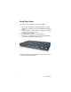
Quick Start Guide Follow these steps to install the IntraCore 65120 switch: 1. 2. 3. 4. 5. Open the box and check the contents. See Chapter 1.1 Package Contents for a complete list of the items included with your IntraCore switch. Install the IntraCore 65120 switch in an equipment or wall rack, or prepare it for desktop placement. Connect the power supply. Connect network devices to the IntraCore 65120. Refer to the User’s Manual on the accompanying CD-ROM for configuration and management capabilities.
Table of Contents Quick Start Guide 2 1. Introduction 1.1 Package Contents 1.2 LEDs 1.3 Front Panel Description 2. Installation and Setup 2.1 Safety Overview 2.2 Recommended Installation Tools 2.3 Power Requirements 2.4 Environmental Requirements 2.5 Cooling and Airflow 2.6 Installation Overview 2.7 Chassis Installation and Placement 2.8 Installing GBIC Interfaces 2.9 Connecting Power 2.
Getting Started Guide
1 Introduction The IntraCore 65120 Thank you for purchasing the Asanté IntraCore 65120 Gigabit switch. The IntraCore 65120 delivers powerful management, user mobility, security, high-availability and multimedia support. The 65120-2G model supports 10 copper Gigabit Ethernet ports and 2 GBIC interface. Each copper port is capable of automatically sensing and working with 10, 100, and 1000 Mbps. The 65120-12G model supports 12 GBIC ports. Multiple LED indicators display the status of each port.
1.2 LEDs After the power is turned on, the power LED will cycle through from amber, to off (for system initialization), to amber again (for system boot up), to finally green (power is up and system is ready).
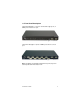
1.3 Front Panel Description The 65120-2G (Figure 1-1) has ten 10/100/1000 copper ports, 2 GBIC ports and a console port. Figure 1-1 65120-2G The 65120-12G (Figure 1-2) has 12 GBIC ports and one console port. Figure 1-2 65120-12G Note: The GBICs are installed normally in the top row; they are installed upside-down in the bottom row.
Getting Started Guide
2 Installation and Setup This chapter explains how to install and connect the IntraCore 65120 to your network. To configure the switch for management, refer to the user’s manual on the IC 65120 CD-ROM. The following guidelines will help you prepare to install the switch in such a way that it has the proper power supply and environment. 2.1 Safety Overview The following information provides safety guidelines to ensure your safety and to protect the switch from damage.
• • Do not tamper with the equipment Examine your work area for potential hazards (I.e. wet floors, ungrounded cables, etc.) For more safety information, please refer to the User’s Manual. 2.2 Recommended Installation Tools You will need the following tools and equipment (not included) to install the IntraCore 65120 switch: • • • Number 1, number 2 and 3/16-inch flatblade screwdrivers Antistatic mat or foam An ESD grounding strap 2.
Avoid direct sunlight, heat sources, or areas with high levels of electromagnetic interference. 2.5 Cooling and Airflow The IntraCore 65120 uses internal fans for air cooling. Do not restrict air flow by covering or obstructing air vents on the sides of the switch. 2.6 Installation Overview Follow these steps to install the IntraCore 65120: 1. 2. 3. 4. 5. Open the box and check the contents. See Chapter 1.1 Package Contents for a complete list of the items included with your IntraCore 65120.
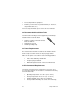
To mount the IntraCore 65120 in an equipment rack: 1. 2. 3. 4. 5. 6. Place the IntraCore 65120 on a flat, stable surface. Locate a rack-mounting bracket (supplied) and place it over the mounting holes on one side of the unit. Use the screws (supplied) to secure the bracket (with a Phillips screwdriver). Repeat the two previous steps on the other side of the unit. Place the switch in the equipment rack. Secure the switch by securing its mounting brackets onto the equipment rack.
2. 3. Place the unit on a flat surface with a minimum area of 434.3 mm x 342.9 mm (17.1” x 13.5”) and support capacity of 10 kg (22 lbs ). Make sure there is enough ventilation space between the IntraCore 65120 and surrounding walls or objects. 2.8 Installing GBIC Interfaces Instructions for installing, removing, and maintaining GBIC interfaces are provided in this section. 2.8.1 Installing a GBIC Note: GBICs are hot-swappable.
3. 4. Slide the GBIC out of the slot. Install the plugs in the GBIC optical bores, and place the GBIC in protective packaging. 2.8.3 GBIC Care and Handling Follow these GBIC maintenance guidelines: • • • • Unnecessary removal and insertion of a GBIC can lead to its premature failure. A GBIC connector has a lifetime of 100 to 500 removals/insertions GBICs are static-sensitive. To prevent ESD damage, follow your normal board and component handling procedures GBICs are dust-sensitive.
2.10 Connecting to the Network The IntraCore 65120 unit may be connected to an Ethernet network with the unit powered on or off. Use the following procedure to make your network connections: 1. 2. Connect network devices to the IntraCore 65120, following the cable guidelines outlined below. After the unit is connected to the network, it can be configured for management capabilities. Please refer to the user’s manual on the IC 65120 CD-ROM. 2.10.
Although 10BaseT requires only pins 1, 2, 3 and 6, Asanté strongly recommends cables with all 8 wires connected as follows: 1000BaseTX requires that all four pairs (8 wires) be connected correctly. Table 2-1 shows the correct pairing of all eight wires.
The console port is used to connect with a terminal using a DB-9 female connector. The setting is 9600-N81. See Table 2-2 for a list of pinouts. Pin Number Signal Name 1 CD Carrier Detect 2 RD Receive Data 3 TD Transmit Data 4 DTR 5 SG 6 DSR Data Set Ready 7 RTS Request to Send 8 CD Carrier Detect 9 RI Ring Indicator Data Terminal Ready Signal Ground Table 2-2 2.10.
Getting Started Guide
Appendix A Troubleshooting and Online Registration In the unlikely event your network does not operate properly, follow the troubleshooting tips below: 1. 2. 3. CHECK YOUR POWER CONNECTION. Is the Power LED on? If not, plug the power cord into another known working AC outlet. CHECK YOUR NETWORK CABLE. Are the LINK LEDs on? If not, check the cable connections. Are the connectors seated correctly in each port? Make sure that the correct type of cable is connected to each port. CHECK YOUR GBIC CONNECTOR.
Getting Started Guide
Appendix B Safety and Regulatory Compliance FCC Compliance Statement NOTE: This equipment has been tested and found to comply with the limits for a Class A digital device, pursuant to part 15 of the FCC Rules. These limits are designed to provide reasonable protection against harmful interference when the equipment is operated in a commercial environment.
Getting Started Guide
Appendix C Defaults and Specifications The IntraCore 65120 is shipped with the following factory default settings and specifications: • • • • • • • • • • • • Switching Method: Store-and-forward System Packets Buffer Size: 1.5MB MAC Address Table: 8000 entries Full-Duplex: Standards-based auto-negotiation enabled VLAN: 64 port-based VLANs, with IEEE 802.1Q tagging Spanning Tree Protocol: 802.1D, enabled Priority: 802.
65120 Series Gigabit Ethernet Switches Getting Started Guide Asanté Technologies, Inc. 821 Fox Lane San Jose, CA 95131 USA SALES 800-662-9686 Home/Office Solutions 800-303-9121 Enterprise Solutions 408-435-8388 TECHNICAL SUPPORT 801-566-8991 Worldwide 801-566-3787 FAX www.asante.com support@asante.com Copyright © 2001 Asanté Technologies, Inc. Asanté is a registered trademark of Asanté Technologies, Inc. The Asanté logo and IntraCore are trademarks of Asanté Technologies, Inc.