RJ45B Module Installation Guide
Copyright Notice Copyright 1994 by Asanté Technologies, Inc. All rights reserved. No part of this manual, or any associated artwork, software, product design or design concept, may be copied, reproduced or stored, in whole or in part, in any form or by any means mechanical, electronic, optical, photocopying, recording or otherwise, including translation to another language or format, without the express written consent of Asanté Technologies, Inc.
Preface • About this Manual on page xii • What Typographic Changes and Symbols Mean on page xiii
About this Manual About this Manual This Installation Guide for the RJ45B Module is part of a set of four installation guides which you will use when you install the NetStacker Hub. The three additional guides you will find useful when installing the hub are ❏ ❏ ❏ NetStacker Hub Installation Guide Asanté RJ21B Module Installation Guide Asanté NetStacker NMM Lite Installation Guide The NMM Lite daughter board is designed specifically for the NetStacker Hub.
Related Documentation What Typographic Changes and Symbols Mean Sometimes it is necessary to give a special meaning or significance to the information in the manual. We do this by displaying a different typeface and often by presenting the text in a different format. Here are examples of the special typefaces and formats used in this manual. We suggest that you become familiar with them here before going on to the rest of the manual. This kind of bolded text is used when special emphasis is neces- sary.
What Typographic Changes and Symbols Mean Procedures and Instructions Many times, the manual provides specific instructions about how to perform a task or configure an application.Where you must perform certain steps in a certain order, the manual provides a formal procedure. All procedures in the manual are made to look different from the regular text to make them easily recognizable and simple to follow. Page xiv 1 Read this first step in this procedure. Be sure to follow all following steps as well.
Asking for Assistance Asanté Technical Support To contact Asanté Technical Support: Telephone (800) 622-7464 (408) 435-0706 Fax (408) 432-6018 Fax-Back* (800) 741-8607 (408) 954-8607 Bulletin Board Service (BBS) (408) 432-1416 Applelink mail/BBS† ASANTE.TECH FTP Archive ftp.asante.com Internet mail‡ support@asante.com * † ‡ Technical Support Hours Tell Us What You Think Please request catalog of contents. Download INDEX.TXT file for catalog of contents.
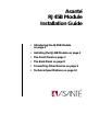
Asanté RJ45B Module Installation Guide • Introducing the RJ45B Module on page 2 • Installing the RJ45B Module on page 3 • The Front Panel on page 7 • The Back Panel on page 8 • Connecting Other Devices on page 9 • Technical Specifications on page 12
Introducing the RJ45B Module Introducing the RJ45B Module The Asanté RJ45B Module is a 24-port, double-height repeater that plugs into the Asanté NetStacker chassis or the AsantéHub 2072 chassis. It is specially designed to accommodate the Asanté NetStacker NMM Lite daughter board which provides the intelligence for the hub. (The RJ45 Module does not accommodate a daughter board.
Grounding Yourself You manage the RJ45B Module from a network management station using AsantéView Lite In-Band and/or Out-of-Band (or AsantéView). All 24 ports on the RJ45B Module are on Segment 1 and cannot be switched to Segment 2. For segment switching capability in a NetStacker stack, use the full-size AH2072 NMM.
Installing the RJ45B Module Installing a Recessed Mini MAU If you plan to use an Asanté recessed Mini MAU, you need to connect it to the recessed AUI connector before you install the module. To install a recessed Asanté Mini MAU: 1 Unscrew the two ejector screws on each side of the module’s front panel and pull out the module approximately four to five inches from the chassis. See Figure 2.
Installing the NMM Lite on the RJ45B Module If you plan to mount an NMM Lite daughter board on the RJ45B mother board, you must do this before you install the RJ45B board. For instructions on how to install the NMM Lite daughter board, on the RJ45B mother board, refer to the NMM Lite Installation Guide. Figure 3 shows an NMM Lite daughter board installed on an RJ45B mother board.
Installing the RJ45B Module Installing the RJ45B Module The NetStacker or AsantéHub 2072 chassis should be installed before you can install the RJ45B Module. To install the RJ45B Module: 1 Remove the module from its antistatic packing, taking care to observe proper antistatic procedures. ∆ 2 Note: Handle the module only by its edges. Do not touch the chips or connectors. Align the module to the edges of the card guides on the slots in the chassis.
Installing the RJ45B Module The Front Panel The RJ45B Module front panel displays the following connectors and LEDs: ❏ Two AUI connectors 24 RJ45 connectors AUI Uplink LEDs 24 Partition LEDs 24 Link/Receive LEDs Segment LEDs (1 and 2) ❏ ❏ ❏ ❏ ❏ Figure 5 shows the RJ45B Module front panel.
The Back Panel Interpreting the LEDs The RJ45B Module front panel LEDs fall into four categories: ❏ ❏ ❏ ❏ Table 2 LED Color/State AUI Uplink AUI port link and partition Port-by-port partition LEDs Port-by-port link/receive LEDs Segment 1 configuration LED RJ45B Module LEDs Meaning Amber On, Blinking Hub has autopartitioned uplink; high collision rate possible. PARTITION LED Amber On, Steady Operator has manually partitioned uplink or trap has been sent. Off Uplink not partitioned.
Connecting to the Backbone Using the AUI Port Connecting Other Devices The RJ45B Module provides two types of connectors for attaching devices: ❏ AUI connectors for connecting to the backbone and to other hubs. One of the connectors accommodates a recessed Mini MAU. RJ45 connectors (24 10BaseT ports) for attaching to network devices ❏ Connecting to the Backbone Using the AUI Port You have two AUI connectors on the front panel—a recessed and a non-recessed connector.
Connecting Other Devices Interconnecting Hubs Using the AUI Port You can interconnect hubs using the AUI Uplink port located on the module’s front panel. Use the appropriate MAU for your backbone. ∆ Asanté provides an RJ45B, BNC, and 10BaseF Mini MAU to accommodate your backbone cabling scheme. To interconnect hubs using the AUI Uplink port 1 Attach the appropriate MAU (if you are not using thick Ethernet) to the AUI port on of the first hub. 2 3 Attach the Ethernet cable.
Connecting a Management Station Using an RJ45 Connector Connecting a Management Station Using an RJ45 Connector To connect the NetStacker Hub to an Asanté Management Station (PC or Mac) for In-Band management: Connect an RJ45 connector on the front panel to an RJ45 port on an Ethernet interface attached to the PC or Macintosh. See Figure 8.
Technical Specifications Technical Specifications This section contains technical specification dealing with: ❏ ❏ ❏ RJ45B Module Technical Specifications RJ45B Module Technical Specifications Out-of-Band Data Specifications Pin-Outs and Cable Specifications The technical specifications for the RJ45B Module are: Standards Supported IEEE 802.3 Ethernet specifications for 10BaseT (UTP) media Data Rate 10 Mbps Maximum Cable Distance 10BaseT (UTP) -- 100m (328 ft.
Out-of-Band Data Specifications Out-of-Band Data Specifications This section contains specification for: ❏ ❏ RS232 Connections Out-of-Band Cable Limitations RS232 Connections Table 4, RS232 Port Interface Pin Assignments lists the pin assignments for a standard RS232 connector.
Technical Specifications Pin-Outs and Cable Specifications This section defines the pin-out assignments and cable specifications for: ❏ ❏ ❏ RJ45B modular jack to wall jack pin-outs RJ45B to RJ45B crossover cables AUI DB15 pin-outs RJ45B Modular Jack to Wall Jack Pin-Outs The pin numbers shown in Figure 7 are for an Asanté 10BaseT card or MAU positioned correctly with the notch on the 8-pin modular jack down. Pin 1 is the left-most pin, and Pin 8 is the right-most pin. See Figure 7.
Pin-Outs and Cable Specifications RJ45B to RJ45B Crossover Cable Figure 8 shows the RJ45B to RJ45B crossover cable. 1 3 2 6 3 1 6 2 Figure 10 ∆ RJ45B crossover cable Note: This manual assumes that straight-through cabling is used for all configurations, except where specifically noted. AUI (DB15) Pin-Outs Table 3 lists the pin numbers, circuit and signal names for the AUI connector.
Technical Specifications In-Band Cable Limitations Table 4 lists the IEEE standards used to determine how networks should be configured when using coaxial cable connections. Table 5 IEEE Standards for Coaxial Cable Connections 10Base2 Thin 10Base5 Coax Ethernet (Thick) (Standard) Data rate 10 Mbits 10 Mbits 10 Mbits Cable length per trunk segment 500m 185m 100m Nodes per trunk segment 100 30 1 Min. distance between nodes 2.5m .5m n/a Max.