
Installation guide


Page 7
Installing the RJ45B Module
The Front Panel
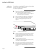
The RJ45B Module front panel displays the following connectors
and LEDs:
❏
Two AUI connectors
❏
24 RJ45 connectors
❏
AUI Uplink LEDs
❏
24 Partition LEDs
❏
24 Link/Receive LEDs
❏
Segment LEDs (1 and 2)
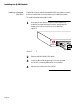
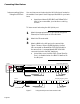
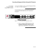
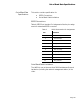
Figure 5 shows the RJ45B Module front panel.
Figure 5 The RJ45B Module front panel
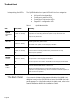
Table 1 identifies the RJ45B Module connectors and LEDs and
their respective functions.
Table 1 RJ45B Module Connector and LED Functions
P
ARTITION
10
BASE
T
P
ORTS
1234 5678 9101112
UPLINK 0
AUI
NetStacker-RJ45
91056781234
L
INK/
R
ECEIVE
L
INK/
R
ECEIVE
P
ARTITION
1234 5678 9101112
UPLINK 0
AUI
91056781234
Connector
Partition LEDs
Link/Receive LEDs RJ45 ports
RJ45 ports
e
cessed
UI Connector
Name Function
AUI connector
Recessed slot
Serves as uplink port to network backbone.
Functions as compartment for housing recessed Mini MAU.
RJ45 connectors 24 ports; each can be connected to Ethernet device, including another hub for
daisy chaining.
AUI Uplink LED If active MAU is attached, this LED remains lit, indicating link exists and is
enabled
Partition LEDs 24 LEDs, indicating partitioned ports.
Link/Receive LEDs 24 LEDs, when lit, indicate link connection; when blinking, indicate packets
received on port.
Segment 1 LED
Segment 2 LED
With NMM Lite daughter board mounted, Segment 1 LED is lit; with AH2072
NMM board, either Segment 1 or Segment 2 LED is lit identifying segment to
which module is connected.
Neither segment LED is lit if module is not connected to segment. Note, even
when module is not connected to segment, repeater still functions.