
Installation guide


Page 14
Technical Specifications
Pin-Outs and Cable
Specifications
This section defines the pin-out assignments and cable specifica-
tions for:
❏ RJ45B modular jack to wall jack pin-outs
❏ RJ45B to RJ45B crossover cables
❏ AUI DB15 pin-outs
RJ45B Modular Jack to Wall Jack Pin-Outs
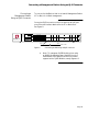
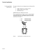
The pin numbers shown in Figure 7 are for an Asanté 10BaseT
card or MAU positioned correctly with the notch on the 8-pin
modular jack down. Pin 1 is the left-most pin, and Pin 8 is the
right-most pin. See Figure 7.
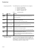
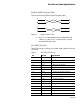
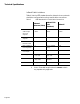
Figure 9 RJ45B wall jack to modular jack pin-outs
1 2 3 4 5 6 7 8
1 TD+ Data Transmit positive
2 TD- Data Transmit negative
3 TD+ Data Transmit positive
4 TD- Data Transmit negative