
Install Instructions

I&M No. V 9611 R5
Installation & Maintenance Instructions
HYDRAMOTOR® PUSH-TYPE LINEAR ACTUATOR
WITH USER SETTABLE LOW FIRE SETTING AND
GENERAL PURPOSE OR WATERTIGHT ENCLOSURE
To prevent the possibility of death, serious injury or property
damage, the Hydramotor® Actuator must be installed and
serviced only by a qualifi ed service technician avoiding the
following hazards:
• Electrical hazard. Turn off all electrical power to
Hydramotor® Actuator.
• Risk of electric shock – More than one disconnect switch
may be required to de-energize the device for servicing.
• Pressure hazard. Depressurize valve and vent hazardous
or combustible fl uid to a safe area before inspection or
removal of the actuator or valve from service.
• Explosion, fi re or toxic gas hazards. Extinguish all open
fl ames and avoid any type of sparking or ignition during
leakage testing.
SERIES
AH4E
Specifi cations
Force Output: 250 lbs
Stroke: 1 1/8” maximum
Electrical Characteristics:
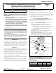
AH4E actuator assembly
Nameplate/electrical
cover
Conduit
knockouts
Cover screw
Valve assembly
Valve stem position indicator
Damper arm
(optional)
Mounting set screw
Figure 1. AH4E Actuator and V710 Valve Assembly
Service Notices
See separate V710 Gas Valve Installation and Maintenance Instructions
for information on: Operation, Positioning, Mounting, Piping, Strainer
or Filter Requirements, Flow Controls, Preventive Maintenance, and
Cause of Improper Operation.
Do not install an actuator with General Purpose Enclosure in a location
subject to weather, wash down, or other sources for water ingress. Use
AH actuators with watertight enclosure for these locations.
DESCRIPTION
AH4E Hydramotors are self-contained linear, push-type actuators which
extend when powered and retract by spring force upon power interruption.
The AH actuator is typically used for control of gas-fi red heating
equipment, commonly to open and close a valve or both a valve and
damper. AH4E actuators position V710 Series gas valve assemblies.
OPERATION
Application of electrical power simultaneously drives an electric pump
and closes a normally-open dump valve and control valve, resulting in up
to 250 pounds of force on the actuator stem. This extends the actuator stem
and attached valve poppet, to open the valve and/or damper.
On reaching the low fi re setpoint, a low fi re switch interrupts power to
the motor while maintaining power to the dump and control valves, thus
stabilizing hydraulic pressure to hold shaft position.
Closing the external high fi re switch causes the actuator to extend beyond
the low fi re point.
Upon reaching the fully extended position, a travel limit switch interrupts
power to the electric motor while maintaining power to the dump valve and
control valves, thus stabilizing hydraulic pressure to hold shaft position.
Opening the high fi re switch de-energizes the control valve allowing the gas
valve to return smoothly to the low fi re position.
Position indicators on both sides of the actuator show the actual position of
the valve stem.
Upon power interruption, the dump valve opens releasing hydraulic
pressure, and allowing the return spring to retract the stem and close the
valve fully. Closing time is one second or less.
ACTUATOR / VALVE COMPATIBILITY
The AH4E series actuator is designed for use only with ASCO V710
valves having V15 or V25 suffi x in catalog number.
OPTIONAL FEATURES
• Damper Shaft Arm Is factory-mounted on RH side. The arm is fi eld-
adjustable to 8 positions and can be switched to the LH side.
» Damper Arm Rating: Drives damper in one direction only. 20
lb maximum at 2.85 in. radius at 20°F to 150°F (-7°C to 65°C )
and 10 lb maximum at -40°F to 20°F (-40°C to -7°C). Damper
spring and linkage must provide suffi cient return force.
» Damper Arm Travel: 2”
• Auxiliary Switch One integral SPDT switch, fi eld adjustable to actuate
atany position of stroke. This is not a safety switch.
• Overtravel Proof-of-Closure Switch A single factory set non-fi eld
adjustable SPDT switch to be used in conjunction withV710 Series
Gas Valves with overtravel seal (V25 suffi x in catalog number).
*Current increases by 20% for 50Hz operation.
WARNING
ASCO Valves®
©ASCO Valve, Inc.® 50 Hanover Road, Florham Park, New Jersey 07932 www.ascovalve.com
E226360 - 5/12
All Rights Reserved.
I&M No. V 9611 R5
Operating Voltage /
Frequency
Current, in Amperes
*
Inrush
Opening Holding
120/60 3.6 2.2 0.18
240/60 1.9 1.2 0.09