I &M No.V5996R8 E21903-4/12 I&M No.
Valve Disassembly WARNING: To prevent the possibility of death, serious injury or property damage, turn off electrical power, depressurize valve, extinguish all open flames and avoid any type of sparking or ignition. Vent hazardous or combustible fluid to a safe area before servicing the valve. NOTE: Determine valve construction AC (Figure 1 on page 3) or DC (Figure 2 on page 4) then proceed as follows: 1. Remove solenoid enclosure, see separate installation and maintenance instructions. 2.
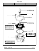
Torque Chart Part Name Solenoid Base Sub---Assembly Bonnet Screws Torque Value 45 ± 5 ft. ---lbs 100 ± 10 in---lbs Torque Value in Newton-- Meters 61,1 ± 6,8 11,3 ±1,1 solenoid base sub---assembly bonnet gasket bonnet screw valve bonnet bleed hole core/diaphragm sub---assembly Locate bleed hole in core/diaphragm sub--assembly approximately 30° from valve inlet body gasket CAUTION Do not damage valve seat in any manner valve body Indicates parts supplied in ASCO Rebuild Kit. Figure 1.
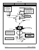
Torque Chart Part Name Solenoid Base Sub---Assembly Bonnet Screws Torque Value 30 ± 5 ft ---lbs 100 ± 10 in---lbs Open end wrench available for solenoid base sub---assembly (order no. K168---146---1) Torque Value in Newton-- Meters 40,7 ± 6,8 11,3 ±1,1 solenoid base sub---assembly Pin holes for special wrench adapter supplied in ASCO Rebuild Kit. For wrench adapter only order no.