
Install Instructions


Page 2 of 4
EASCO Valve, Inc.R 50 Hanover Road, Florham Park, New Jersey 07932 www.ascovalve.com
I&M No. V 5996 R7
Valve Disassembly
WARNING: To prevent the possibility of
death, serious injury or property damage,
turn off electrical power, depressurize valve,
extinguish all open flames and avoid any
type of sparking or ignition. Vent hazardous
or combustible fluid to a safe area before
servicing the valve.
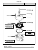
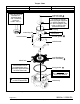
NOTE: Determine valve construction AC (Figure 1 on
page 3) or DC (Figure 2 on page 4) then proceed as follows:
1. Remove solenoid enclosure, see separate installation
and maintenance instructions.
2. For AC Construction, unscrew solenoid base
sub---assembly. For DC Construction, unscrew
solenoid base sub---assembly with special wrench
adapter provided in ASCO Rebuild Kit. For wrench
adapter only, order kit No.K218---949. NOTE: For
alternate type open end wrench, order kit
No.K168---146---1 which is available for solenoid base
sub---assembly removal or replacement.
3. Remove bonnet screws, valve bonnet, bonnet gasket,
core/diaphragm sub---assembly and body gasket.
4. All parts are now accessible to clean or replace. If parts
are worn or damaged, install a complete ASCO
Rebuild kit.
Valve Reassembly
1. Lubricate bonnet gasket and body gasket with a light
coat of DOW CORNINGr 200 Fluid lubricant or an
equivalent high---grade silicone fluid.
2. Apply a light coat of TFL 50r Dry Lube to:
S Valve seat
S Valve body flange where diaphragm assembly
contacts the valve body and body gasket.
S Internal surface of valve bonnet where
diaphragm assembly contacts bonnet when
valve is in the energized (open position).
IMPORTANT: If valve has been disassembled for inspection
and cleaning only and a Rebuild Kit is not being installed,
lubricate the following with TFL 50r Dry Lube:
S Diaphragm assembly on both sides.
S Main disc base of core/diaphragm sub---assembly.
S Pilot disc at base of core assembly.
CAUTION: Do not distort hanger spring between
core assembly and diaphragm assembly when
lubricating pilot disc.
3. Replace body gasket and core/diaphragm sub---assembly
with closing spring attached. Locate bleed hole in
core/diaphragm sub---assembly approximately 30_ from
the valve inlet.
4. Replace valve bonnet and bonnet screws (6). Torque
screws in a crisscross manner to 100 ±10 in---lbs [11,3
± 1,1 Nm].
5. For AC construction, replace bonnet gasket and
solenoid base sub---assembly. Torque solenoid base
sub---assembly to 45 ± 5 ft---lbs [61,1 ± 6,8 Nm] For DC
construction refer to separate “Solenoid Installation
and Maintenance Instructions” for lubrication
instructions; then install bonnet gasket, housing and
solenoid base sub---assembly. Torque solenoid base
sub---assembly to 30 ± 5 ft---lbs [40,7 ± 6,8 Nm].
6. Replace solenoid (see separate instructions) and make
electrical hookup.
WARNING: To prevent the possibility of
death, serious injury or property damage,
check valve for proper operation before
returning to service. Also perform internal seat
and external leakage tests with a
nonhazardous, noncombustible fluid.
7. Restore line pressure and electrical power supply to
valve.
8. After maintenance is completed, operate the valve a
few times to be sure of proper operation. A metallic
click signifies the solenoid is operating.
ORDERING INFORMATION
FOR ASCO REBUILD KITS
Parts marked with an asterisk (*) in the
exploded views are supplied in Rebuild Kits.
D When Ordering Rebuild Kits for ASCO Valves,
order the Rebuild Kit number stamped on the valve
nameplate.
+ If the number of the kit is not visible, order by
indicating the number of kits required, and the Catalog
Number and Serial Number of the valve(s) for which they
are intended.
I&M No. V 5996 R8