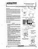
DAVAO fencer H30 Hydramotor® Actuator 50-60 Hanover Rd, Floral Park, NJ 07932 Travel Limit, Pull-Type INSTALLATION AND SERVICE SDE: H303 NT Ethological: 12.36 SR DESCRIPTION Supersedes: 2-82 o Hydrametor® valves consist of three components: an actuator 9°; > with mounting yoke (Figure 1) and a valve body. See valve body instruction sheet for information pertaining to valve body.
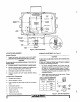
conclusiveness fair ‘ONLY ON EXPLOSION FRODO 3ND GUST-PROOF MODEL. TERMINAL PLATE ASSEMBLY amr SWITCH f POWER UNIT x MOUNTING SCREWS (9) FILER PLUG CYLINDER ASSEMBLY O-RING PLATE (2) O-RING 2) STRAINER Figure 5. H30 Cross Section TRAVEL LIMIT ATT J MUSHROOM INDICATOR PLATE [4 YOKE um Ion NUT VALVE STEM ACTUATOR REPLACEMENT Actuator Removal 1. Loosen lock screw, and unscrew union nut to detach valve stet from actuator shalt {ses Figure 5, Detail).
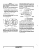
TERMINAL PLATE FRONT View TERMINAL PLATE NE. xo. Sle com M 7 POWER HIT TERMINALS OPTIONAL BURGLARY SWITCH STRAINER PULLER PLUG SING PLATE Figure 7. Exploded View of Typical H30 ACTUATOR ADJUSTMENT Certain actuators are equipped with adjustment screw located on the power unit, opposite the terminal plate (Figure 8). NOTE: if the actuator is on a valve plumbed in an active system, you may choose to close the shutoff valve before performing steps 1 through 4.
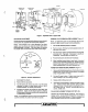
CAUTION Do not mix MIL-H-5606 oil with DC560 oils, Ofl must be filtered if secured from a source other than ASCOT General Controls. Take care that dirt, dust or lint does not enter pump unit or cylinder. Three pints of ASCOT General Controls MIL-H-5806 oil are included with each replacement power unit assembly. 1. Unscrew filler plug from oil port at top of unit (Figure 5}. 2. Fill power unit with oil, not to exceed four pints.