
Install Instructions

Page 1 of 4
50 Hanover Road, Florham Park, New Jersey 07932 www.ascovalve.com
All Rights Reserved.
E184988
Installation & Maintenance Instructions
SERIES
I&M No.V8500R3
FUEL GAS SERVICE
2-WAY DIRECT - ACTING SOLENOID VALVES
NORMALLY CLOSED OPERATION Ċ 3/8I, 1/2I, 3/4I, OR 1I NPT
K3A4
K3A5
Service Notice
Except for coil replacement, the Series K3A4 and K3A5 are
not repairable. When any performance problems are
detected during routine inspection, replace valve
immediately.
DESCRIPTION
Series K3A4 and K3A5 valves are 2-way normally closed
direct-acting solenoid valves designed for fuel gas service.
Valve bodies are made of rugged aluminum with trim and
internal parts made of steel and stainless steel. Series K3A4
valves are designed for low pressure, while Series K3A5 are
designed for medium pressure. These valves are provided
with a general purpose junction box solenoid enclosure.
Provisions for Pressure and Seat Leakage Testing
Series K3A4 and K3A5 valves are provided with two 1/8I NPT
tapped and plugged holes (pressure taps). The upstream
tapped and plugged hole is on the side of the valve body;
downstream on the bottom of the valve body. One upstream
for pressure testing; one downstream for seat leakage testing.
Leakage testing frequency shall be at least annually in
accordance with NFPA-86 or original equipment
manufacturer recommendations. For instructions, refer to
section on Testing for Internal (Seat) Leakage and Figure 3.
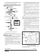
Figure 1. Provisions for pressure and seat leakage testing.
Partial view of valve body showing location
of tapped and plugged holes for pressure
and seat leakage testing
on bottom of valve body
for downstream seat
leakage testing
on side of valve body
for upstream pressure
testing
Pipe plugs are 1/8I NPT
(use 3/16I hex key wrench)
Tapped and plugged hole
(pressure tap)
Tapped and plugged hole
(pressure tap)
OPERATION
Normally Closed: Valve is closed when solenoid is
de-energized; open when energized.
Note: No minimum operating pressure differential required.
INSTALLATION
Check nameplate for correct catalog number, pressure,
voltage, frequency, and service. Never apply incompatible
fluids or exceed pressure rating of the valve. Installation and
valve maintenance to be performed by qualified personnel.
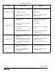
Temperature Limitations
Series
Coil Class
Wattage
Nominal
Fluid
Temperature
Ambient
Temperature
Range
K3A4
K3A5
10.5 / F
16.7 / N
77_F (25_C)
-40_F (-40_C) to
175_F (80_C)
Positioning
Valve must be mounted with solenoid vertical and upright or
in a horizontal position only.
Piping
CAUTION: Piping must comply with applicable
local and national codes and ordinances, including the
National Fuel Gas Code ANSI Z223.1/NFPA No. 54.
Connect piping to valve according to flow arrow on bottom of
valve body. Apply pipe compound sparingly to male pipe
threads only. If applied to valve threads, the compound may
enter the valve and cause operational difficulty. Avoid pipe
strain by properly supporting and aligning piping. When
tightening the pipe, do not use valve or solenoid as a lever.
Locate wrenches applied to valve body or piping as close as
possible to connection point. Valve should be checked for
external leakage at piping connections after installation, see
Testing for External Leakage section.
CAUTION: To avoid damage to the valve body, DO
NOT OVERTIGHTEN PIPE CONNECTIONS. If PTFE
tape, paste, spray, or similar lubricant is used, use extra
care when tightening due to reduced friction.